Dust Guard – Broken-bag Detector
DUSTguard – Broken-bag Detector.
- Low-cost broken-bag detector for filter leaks
- Contact measurement / Passive / No moving parts
- Detection of only moving material – not influenced by deposits
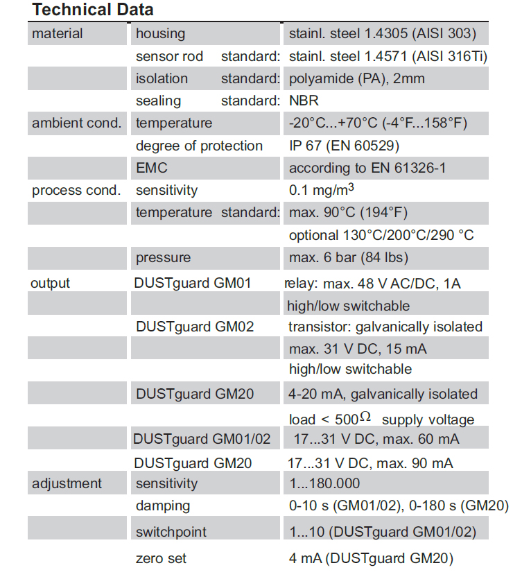
- Detects all dust types, Sensitivity 0.1 mg/m3
- Output Signal: (4…20 mA) or Relay
- Compact design in Stainless Steel housing
- Simple commissioning / Plug & Play
- Reliable, long-term stable, maintenance-free
- High-temperature version up to 290 degrees C
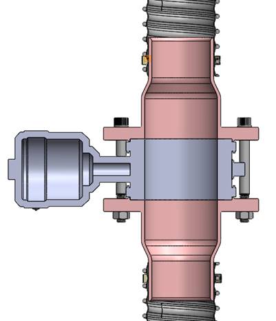
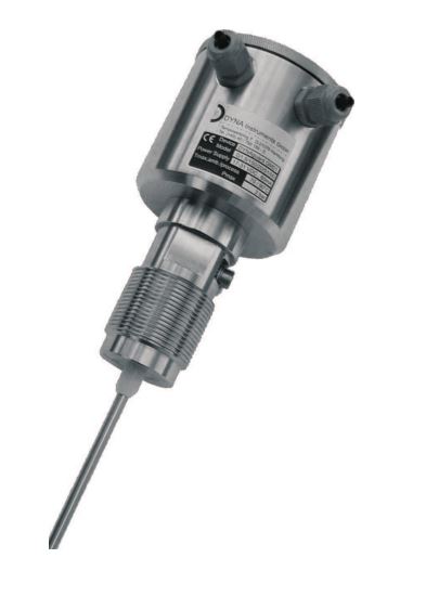
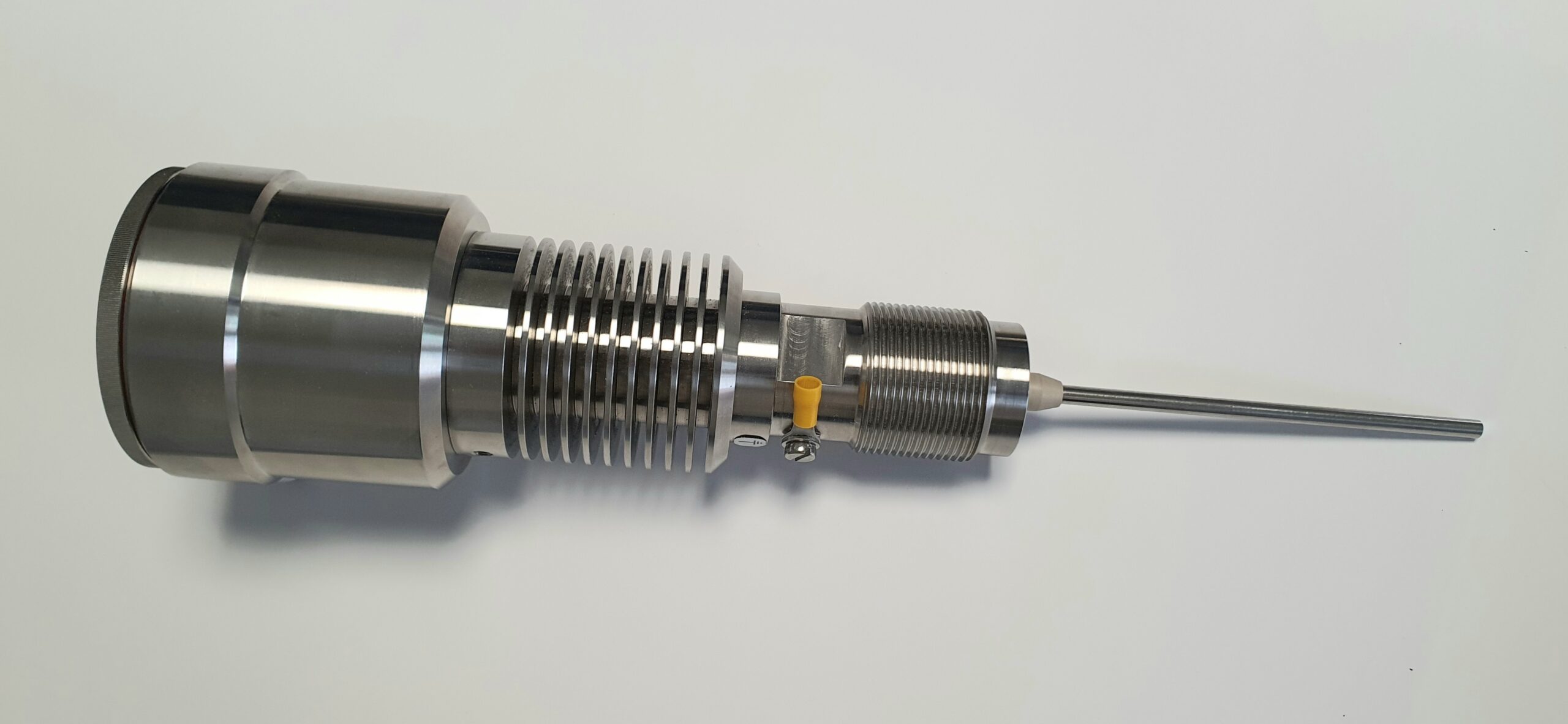
The DUSTguard is used for the detection or trending of high level emissions or filter malfunctions like broken bags. The technology is based on a modified triboelectric principle detecting particles interacting with the sensing rod and such particles just passing by the rod. Build up on the rod surface will not be detected, only moving particles generate a flow rate proportional signal which is monitored by the electronics. Three electronics versions are available with analog (GM20), relay (GM01) or transistor (GM02) output. Signal damping is adjustable by the user. The sensor length should be between 1/3 to 2/3 of the duct diameter, 800mm maximum. Installation is done on the clean gas side downstream the filter on a metal duct by welding on a thread bush, boring through the duct wall and screwing in the DUSTguard. Upstream and downstream of the sensor, at least three duct diameters should be straight without any fittings like valves or dampers. Comissioning is simple and requires no tools or specialized equipment.
What do you want to do?
Use
The DUSTguard is used for the detection or trending of high level emissions or filter malfunctions like broken bags. The DUSTguard technology is based on a modified triboelectric principle detecting particles interacting with the sensing rod and such particles just passing by the rod. Build up on the rod surface will not be detected, only moving particles generate a flow rate proportional signal which is monitored by the electronics. Three electronics versions are available with analog (GM20), relay (GM01) or transistor (GM02) output.
Adaptation is done under normal conditions by switches and potentiometer, DUSTguard’s alarm level (GM01, GM02) can be set above this background. Signal damping is adjustable by the user.
Function
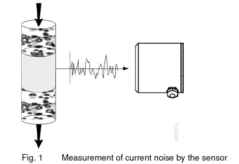
The applied technology is based on the electrostatic principle, whereby the physical effect of the electrical charges of the solid particles is utilised. The particles electrically charged by natural means, such as by friction or fracture, generate (influence) a charge signal against the grounded transport channel when they pass the sensor surface.
Due to statistical fluctuations in the flow of particles, a current noise results, which increases both with the particle concentration and with the transport velocity. The electronics set the level of this noise in relation to the mass throughput or concentration. The adjustment of the process is done manually via internal control elements.
Deposits on the sensor surface are not detected; only moving particles generate a signal. Caking, for example, therefore has no impact.
The device cannot be used with products that form an electrically conductive layer on the sensor system as a result of abrasion or caking.
Mounting and Installation
Follow the nationally applicable installation guidelines.
Ensure a proper installation so that the IP classification is maintained.
The device may only be used as intended. The interconnection with external electrical equipment must be checked for compliance with the technical regulations.
The device is protected against the penetration of particulate matter and water as indicated by an IP classification (see chapter 9). Protect the device against excessive contamination from particulate matter and water (such as during outdoor use), especially if this contamination exceeds the classification.
For process temperatures above 80°C, the sensor electronics must be thermally isolated from the process so that the permissible ambient temperature (see chapter 3.3) is maintained. Special device versions are available for high process temperatures. Do not place the head housing above any hot pipes so as to avoid exposure to rising heat. Thermal insulation may not enclose the head housing as this may lead to overheating of the electronics and ultimately to malfunctions or destruction of the electronics.
The head housing must be heated at temperatures below -20°C.
The head housing may heat up in direct sunlight. In such a case, provide shading in the form of a weather protection hood.
Avoid vibrations of the conveyor pipeline at the site of installation.
The installation of the electric circuit must be done in accordance with the applicable regulations (proof of the installer’s expertise, protected routing, etc.).
Ensure that the provided operating voltage corresponds to the information in the technical specifications (see chapter 3.3.1).
The housing and connection may only be opened in a voltage-free state. The PE connection is to be made with low inductance with the PE of the system in accordance with the local regulations.
The connecting pipelines must be permanently installed outside of the operating equipment. All cable and wire entries must be closed in accordance with the manufacturer’s specifications.
Avoid electrostatic charges. Ground the device. The grounding is different depending on the device type:
In general, the measuring principle allows for installation in any position (horizontal, vertical, oblique). The measurement result shows few fluctuations over time when the material flows through the sensor as uniformly as possible. An installation where the product flows vertically downwards through the sensor is therefore preferred (especially for more concentrated currents at low transport velocities). Provide the following calming sections if possible:
• Inlet section 10x inner diameter with pneumatic conveyance, 2x inner diameter in the event of a falling process.
• Outlet section 5x inner diameter with pneumatic conveyance, 2x inner diameter in the event of a falling process.
Technical Data
Application Examples
Click on a desired application example to navigate to a detailed description.

Global Technology Systems
P.O. Box 799 Shalimar, FL 32579. USA
(850) 651-3388
[email protected]

