PicoFlow –
Continuous flow measurement
at low solid/air ratios
- In pneumatic applications for material flow rates of up to 100 kg/h
(depending on application) - In free-fall with a drop speed of at least 2 m/s (approx. 25 cm drop height)
- In cases where dust measuring instruments cannot cope and flow rate
measuring instruments are overspecified
What do you want to do?
Use
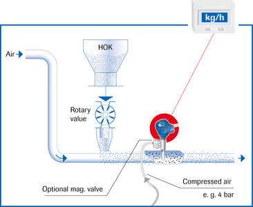
PicoFlow is particularly good in pneumatic applications but will also work reliably in free-fall applications with drop speeds of at least 2 m/s.
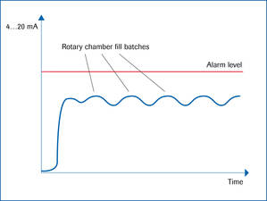
The measuring system delivers absolute measurements (after calibration)
in g/h or kg/h.
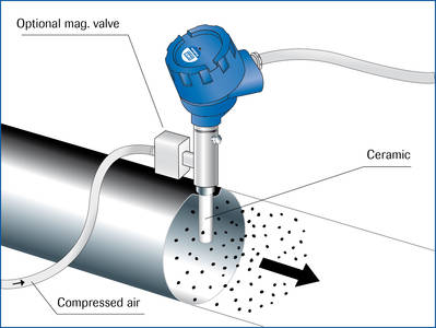
A special air purging system is also available as an option.
This is used for materials which tend to bake onto surfaces.
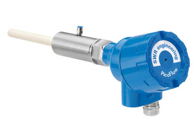
Function
A ceramic coating on the very short antenna prevents sensor wear.
Specially developed hardware and software allows the measurements to be linearised.
Mounting and Installation
It should be installed as far as possible away from curves and other fittings such as valves and slides.The distance between the sensor rod and fittings in the duct should be at least three times the duct diameter in every flow direction.
Non-metallic ducts must be cased with a metal sleeve, a metal foil or a tight-mesh metal grille over a length of at least five times the duct diameter.
After deciding the installation location, drill a hole in the duct wall where the supplied weld-on socket can be welded perpendicular to the pipe. Then screw the sensor rod into the socket using the screw-in thread.
Technical Data
| Sensor | Measurement range | From 100 g/h to 100 kg/h (depends on application) |
|---|---|---|
| Process temperature | Standard: 150 °C; Optional: max. 500 °C | |
| Pressure | Max. 2 bar (Optional: up to 25 bar) | |
| Flow velocity | Min. 2 m/sec | |
| Humidity | 60 % RH or less (non-condensing) | |
| Measurement principle | Electrodynamics | |
| Ambient temperature | -20 … +60 °C | |
| Sensor rod | Material: Stainless steel, AL2O3 ceramic 99,7 %; Length: depends on application | |
| Housing material | Aluminium | |
| Protection type | IP 66; ATEX: Cat. 1/2 GD | |
| Electrial connection | Connection chamber DIN M 20 | |
| Switch output measurement alarm | Relay with switchover contact – max. 250 V/AC, 1A Not on EX devices Cat. 1 and 2 |
|
| Weight | Ca. 1.5 kg | |
| Transmitter (field housing) | Power supply | 110/230 V, 50 Hz (optional 24 V DC) |
| Power consumption | 20 W / 24 VA | |
| Protection type | IP 65 to EN 60 529/10.91 | |
| Ambient temperature | -10 … + 45 °C | |
| Dimensions | 258 x 237 x 174 (W x H x D) | |
| Weight | approx. 2.5 kg | |
| Interface | RS 485 / RS 232 C (ModBus) | |
| Cable screw connectors | 3 x M 16 (4.5 – 10 mm Ø) | |
| Connection terminals cable cross-section | 0.2 – 2.5 mm² [AWG 24-14] | |
| Current output | 4 … 20 mA (0 … 20 mA), load < 500 Ω | |
| Switch output measurement alarm | Relay with switchover contact – max. 250 V AC, 1 A | |
| Data backup | Flash memory | |
| Pulse output | Open collector – max. 30 V, 20 mA | |
| Transmitter (DIN rail) | Power supply | 24 V DC ± 10 % |
| Power consumption | 20 W / 24 VA | |
| Protection type | IP 40 to EN 60 529 | |
| Ambient temperature | -10 … +45 °C | |
| Dimensions | 23 x 90 x 118 (W x H x D) | |
| Weight | Approx. 172 g | |
| Connection terminals cable cross-section | 0.2 – 2.5 mm² [AWG 24-14] | |
| Current output | 4 … 20 mA (0 … 20 mA), load < 500 Ω | |
| Switch output measurement alarm | Relay with switchover contact – max. 250 V AC, 1 A | |
| Data backup | Flash memory | |
| Pulse output | Open collector – max. 30 V, 20 mA |
Global Technology Systems
P.O. Box 799 Shalimar, FL 32579. USA
(850) 651-3388
Info@onthelevel.com
Partners