
Solid flow measurement
SolidFlow 2.0 Mass Flow Meter
A microwave sensor for continuous, online mass flow measurement of dust, powder and granules in metal pipes, in free fall or pneumatic conveying.

- Works in free fall and pneumatic conveying
- Measures almost all dust, powder and granules
- Nothing installed in the material stream
- Simple retrofit with a weld-on socket
- Throughput measurement up to 20 t/h
- Active roping compensation for reliable readings
- Calibrated in place at the push of a button
- ATEX certified
Use
Where SolidFlow 2.0 fits
SolidFlow 2.0 is a sensor developed specifically for measuring the flow rate of solids conveyed in metal ducts. It has been tested successfully for online measurement of:
- All types of dust, powder and granules
- Grain sizes between 1 nm and 1 cm (0.4 in)
- Pneumatically conveyed materials
- Material in free fall after mechanical conveying systems
The sensor is wear-resistant, and commissioning is simple.

Function
How the microwave measurement works
The SolidFlow 2.0 sensor uses microwave technology and is used exclusively in metal piping. The measuring field is created by coupling the microwave with the metal pipe itself.
The microwave coupled into the pipe is reflected by the solid particles and received by the sensor. The received signals are evaluated by frequency and amplitude, so the sensor works much like a particle counter, counting moving particles per unit of time. Frequency-selective analysis ensures that only moving particles are measured.
Active roping compensation breaks the measuring signal down into its frequency spectrum, which lets the sensor compensate for the effects of roping.
Calibration takes place with the sensor installed: push a button and enter the reference quantity.


Mounting and installation
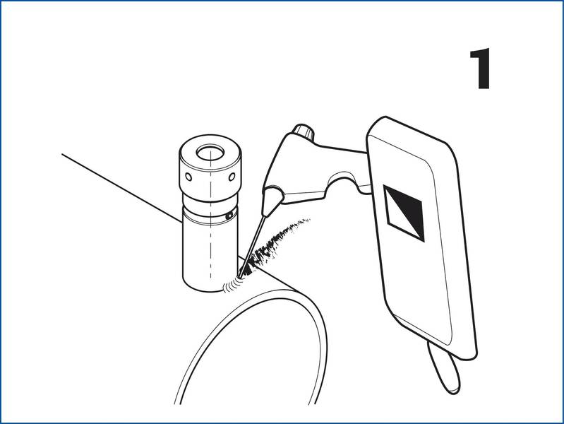
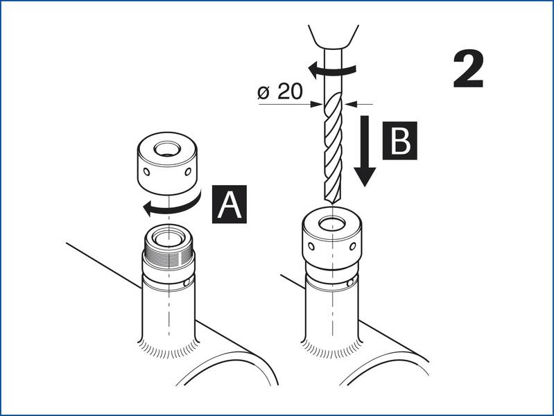
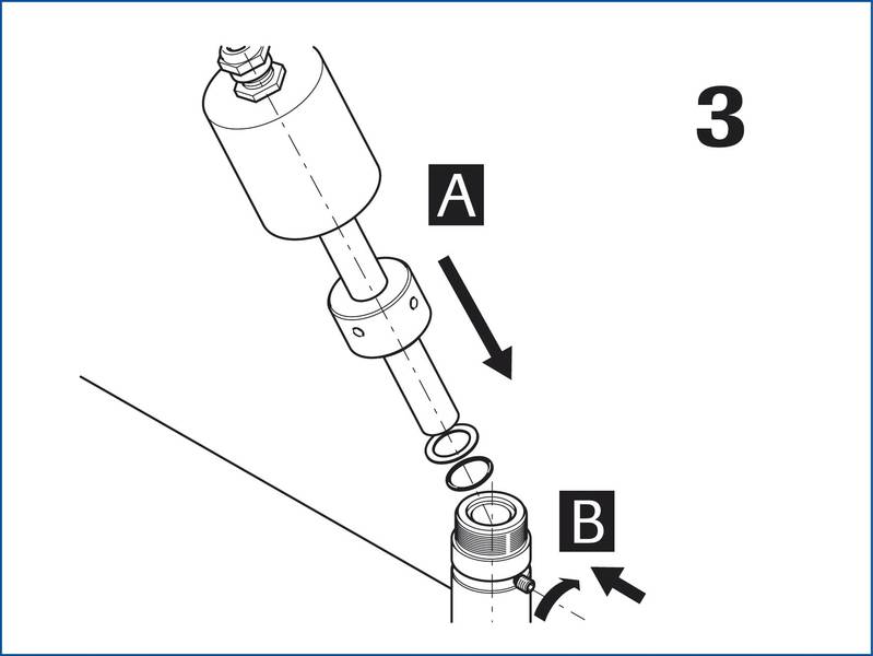
Retrofit in four steps
The installation location is specified based on the conveying inlet and outlet paths.
- Weld the sensor bracket (welding socket) at the specified location.
- Drill a 20 mm (0.79 in) hole through the bracket and the pipe wall.
- Adjust the sensor to the wall thickness and insert it.
- Fix the sensor with the coupling nut.
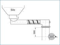
Pipes over 200 mm (7.9 in) use 2 or 3 sensors per measuring point, arranged at 90° or 120° to each other. In free-fall applications, such as after screw conveyors or rotary feeders, an inlet path (fall height) of at least 300 mm (11.8 in) is ideal. Shorter inlet paths are possible by agreement.
Commissioning
Commissioning is done through the FME evaluation electronics, with menu-driven input of parameters such as measuring range, physical units and signal damping. Outputs are 4–20 mA current and pulse (open collector). Menus are available in English, German and French.
Technical data
SolidFlow 2.0 specifications
Imperial values are converted from the manufacturer's metric data. Confirm critical values against the product information PDF.
| Housing | Stainless steel 1.4571 (316Ti) |
|---|---|
| Protection category | IP 65, DustEx 20 or GasEx (option) |
| Operating temperature | Sensor front end: −20 to +80 °C (−4 to +176 °F)Optional: −20 to +200 °C (−4 to +392 °F)Sensor electronics: 0 to 60 °C (+32 to +140 °F) |
| Max. working pressure | 1 bar (14.5 psi), optional 10 bar (145 psi) |
| Working frequency | K-band 24.125 GHz (±100 MHz) |
| Transmitting power | Max. 5 mW |
| Weight | 1.3 kg (2.9 lb) |
| Dimensions | Ø 60 mm, Ø 20 mm, L 271 mm (Ø 2.4 in, Ø 0.8 in, L 10.7 in) |
| Accuracy | ±2–5% in calibrated range |
| Power supply | 110/230 V, 50 Hz (optional 24 V DC) |
|---|---|
| Power consumption | 20 W / 24 VA |
| Current consumption | Max. 1 A at 24 V |
| Protection category | IP 65 according to EN 60529 |
| Operating temperature | −10 to +45 °C (+14 to +113 °F) |
| Enclosure dimensions | 258 × 237 × 174 mm W × H × D (10.2 × 9.3 × 6.9 in) |
| Weight | Approx. 2.5 kg (5.5 lb) |
| Interface | RS 485 / RS 232 C (Modbus) |
| Cable glands | 3 × M16 (4.5–10 mm Ø) |
| Screw terminals | 0.2–2.5 mm² (AWG 24–14) |
| Current output | 4–20 mA (0–20 mA), load < 500 Ω |
| Alarm relay output | Relay with switching contact, max. 250 V AC, 1 A |
| Pulse output | Open collector, max. 30 V, 20 mA |
| Data storage | Flash |
| Size | 98 × 64 × 35 mm W × H × D (3.9 × 2.5 × 1.4 in) |
|---|
Application examples
SolidFlow 2.0 in real processes


Common questions
SolidFlow 2.0 FAQ
What materials can SolidFlow 2.0 measure?
Almost all types of dust, powder and granules, with grain sizes up to 1 cm (0.4 in), whether pneumatically conveyed or falling freely after mechanical conveying equipment.
Does SolidFlow 2.0 work in plastic or non-metal pipes?
No. The measuring field is created by coupling the microwave with the metal pipe, so the sensor is used exclusively in metal piping.
How is SolidFlow 2.0 calibrated?
Calibration is done with the sensor installed, by pushing a button and entering a reference quantity.
What outputs does SolidFlow 2.0 provide?
A 4–20 mA (or 0–20 mA) current output, an open-collector pulse output, an alarm relay, and an RS 485 / RS 232 C Modbus interface.
Can SolidFlow 2.0 measure large-diameter pipes?
Yes. On pipes over 200 mm (7.9 in), 2 or 3 sensors are used per measuring point, arranged at 90° or 120° to each other.
How accurate is SolidFlow 2.0?
±2–5% within the calibrated range.
Talk with GTS
Is SolidFlow 2.0 right for your material?
Tell us what you're conveying, the pipe size and how it moves. We'll confirm whether SolidFlow 2.0 fits or recommend a better measurement principle.