SF METER
Flow Measurement of bulk solids with microwave-technology
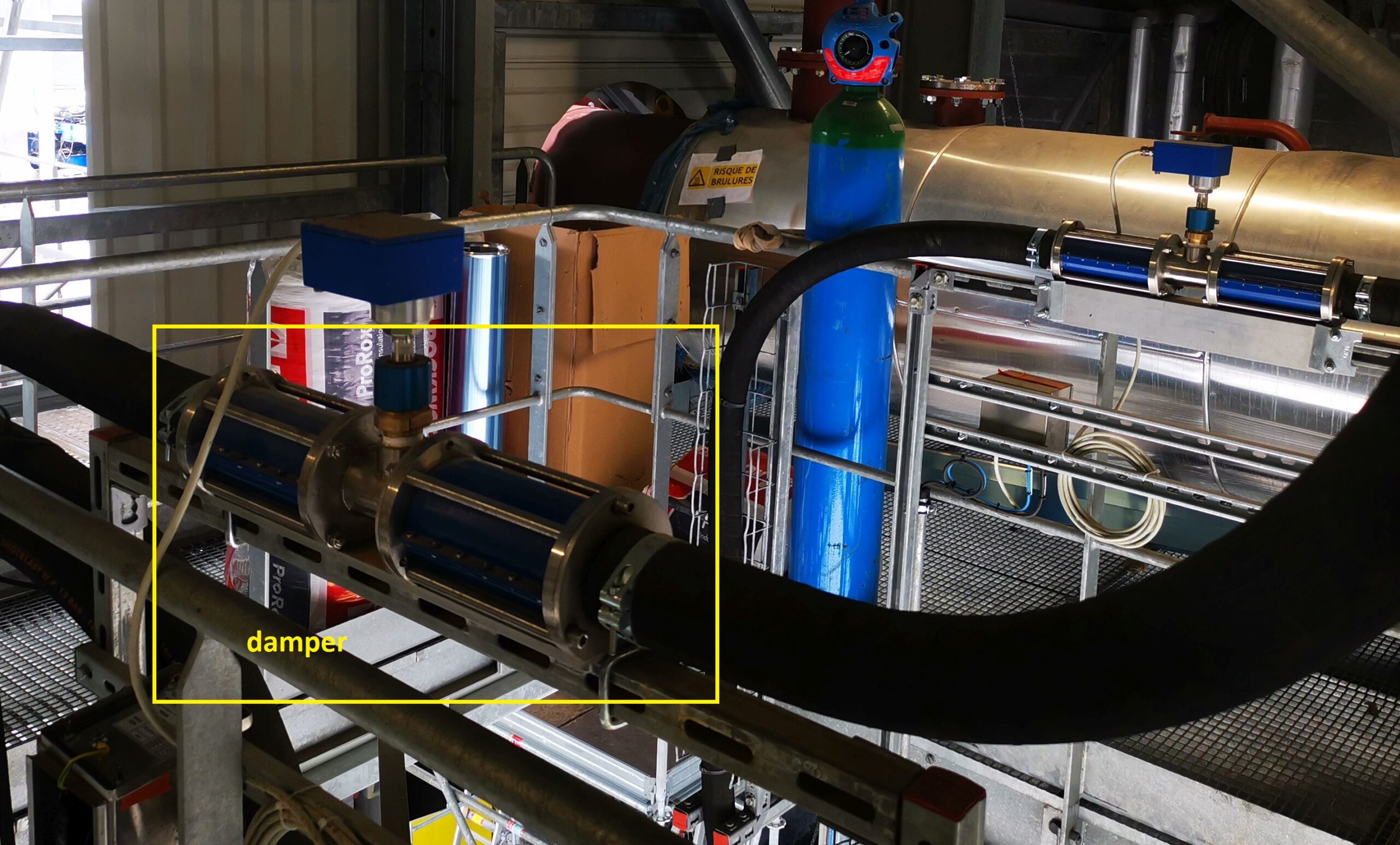
- For pneumatic conveying and freefall processes (grams/min to tph)
- Easy installation and start up for flow ranges 0 – 40 tph depending on material
- Integral solids flow measurement for all types of powders, granules, flakes, chips, etc.
- Install on any size tube or pipe diameter (chutes and ducts need to be reviewed)
- Long-term stable, reliable, robust
- Sensor supply for connections up to 1000 m
- Galvanically separated RS485-Interface for PLC-Connection
- Analog 4-20 mA output, RS485 and alarm relay

What do you want to do?
Use
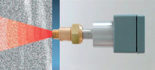
SF METER (Solids Flow) uses the principle of the Doppler effect.
A microwave signal is emitted, thereby generating an electromagnetic field inside the pipes.
The particles passing in movement in this field generate a signal that varies in amplitude and in frequency.
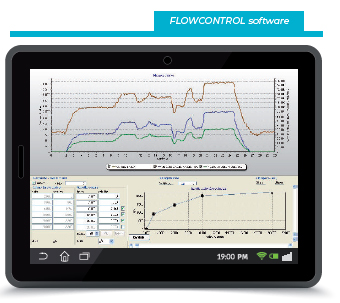
Dynamic flow:
The rate of flow is deduced from a mathematical analysis
combined with a calibration (with real measures).
Flow no Flow:
The threshold can be defined between 0 and 100% of flow
A “switch” is activated when the sensor detects a superior or
inferior fixed threshold.
Function
Beyond the working principle, the technology developed for SF METER allows the equipment to compensate for
variations in:
- Concentration
- Speed of particles
- Granulometrics
- Temperature
FOR BETTER PRECISION.
FOR BETTER REPEATABILITY.
FOR BETTER STABILITY OVER TIME.
Contactless measurement
Very easy-to-use device
No maintenance
No remote electronic handling
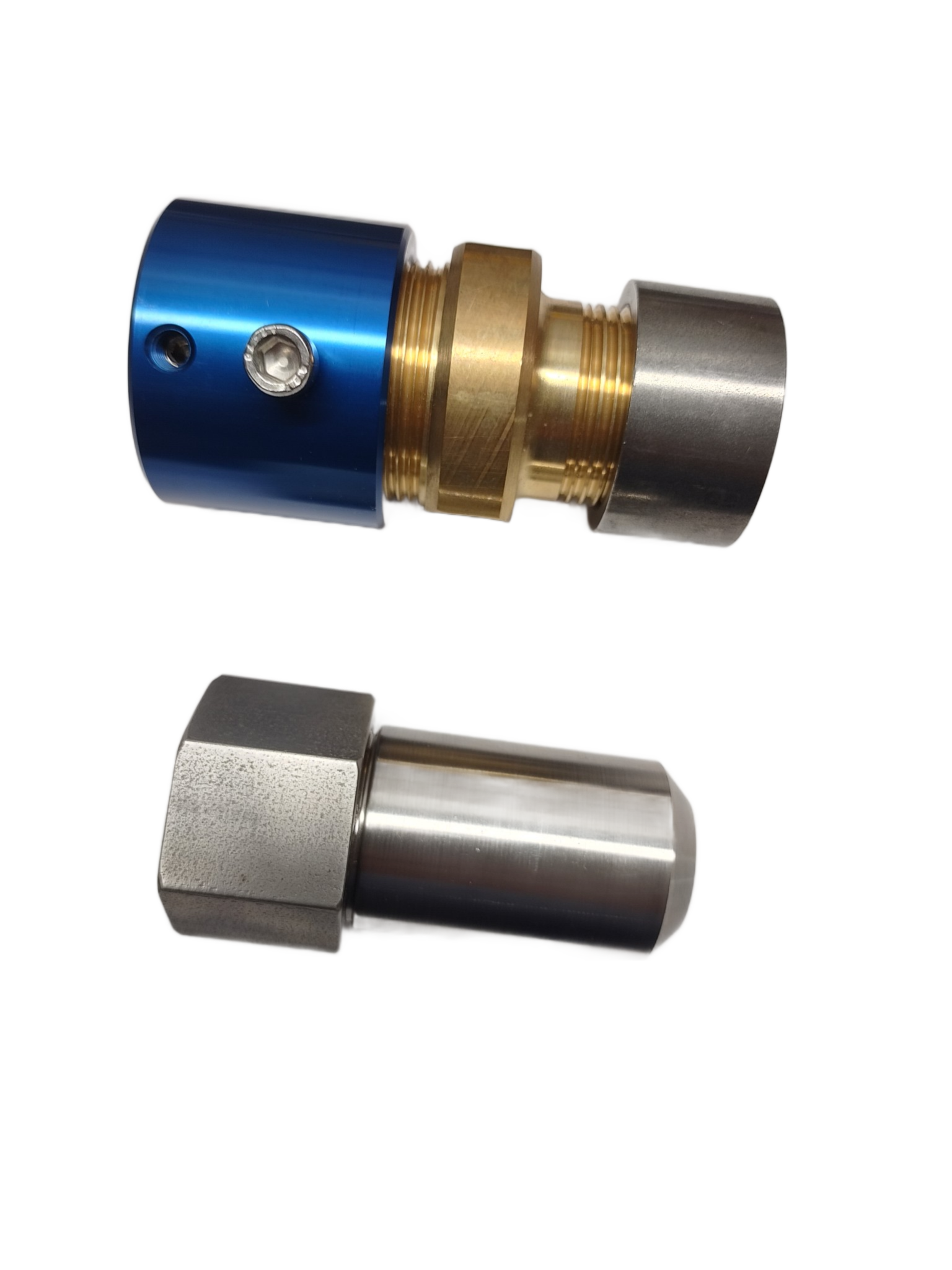
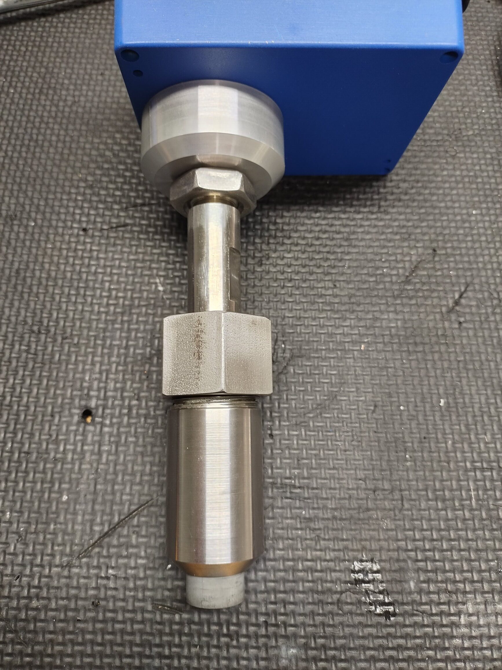
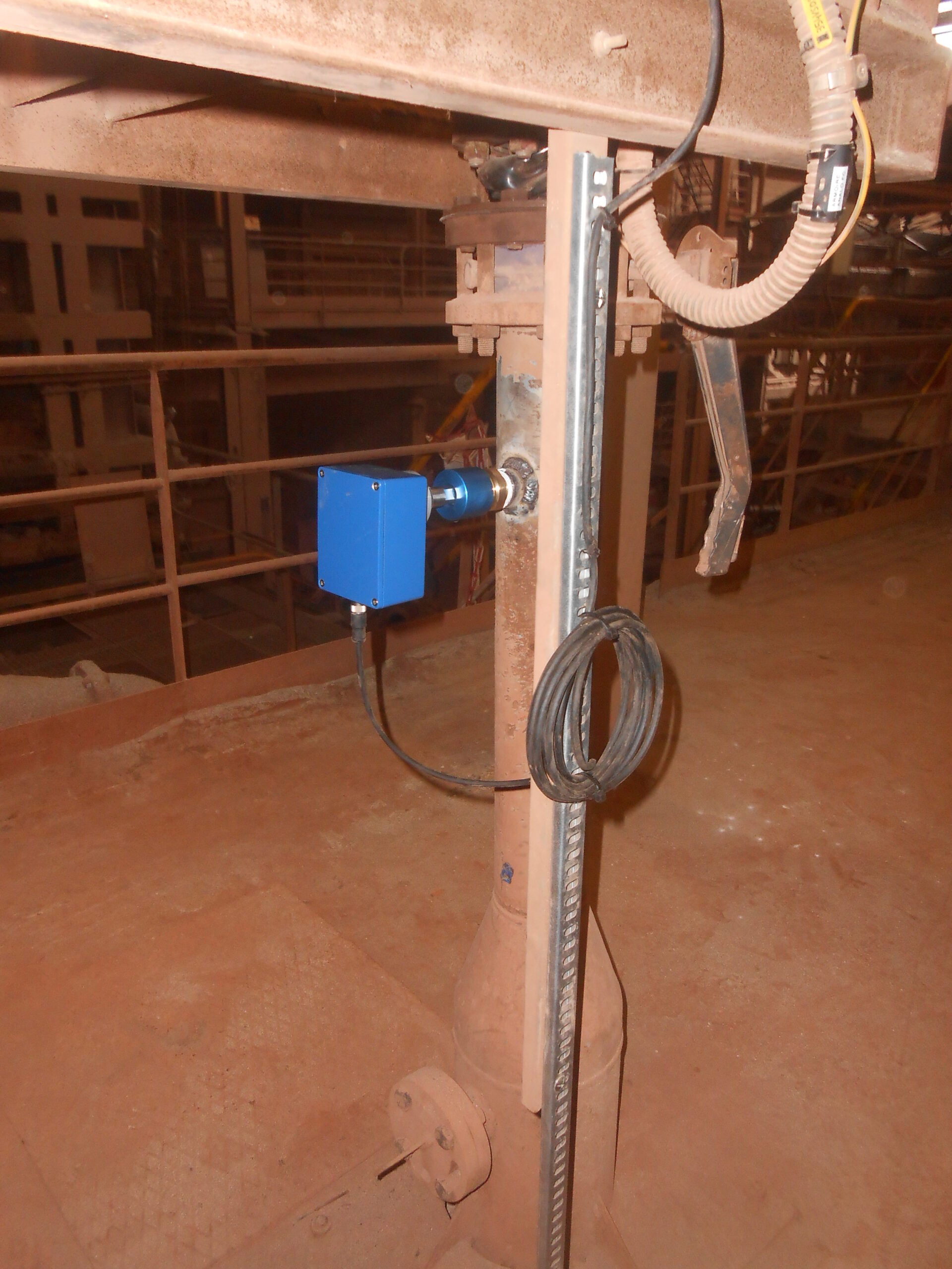
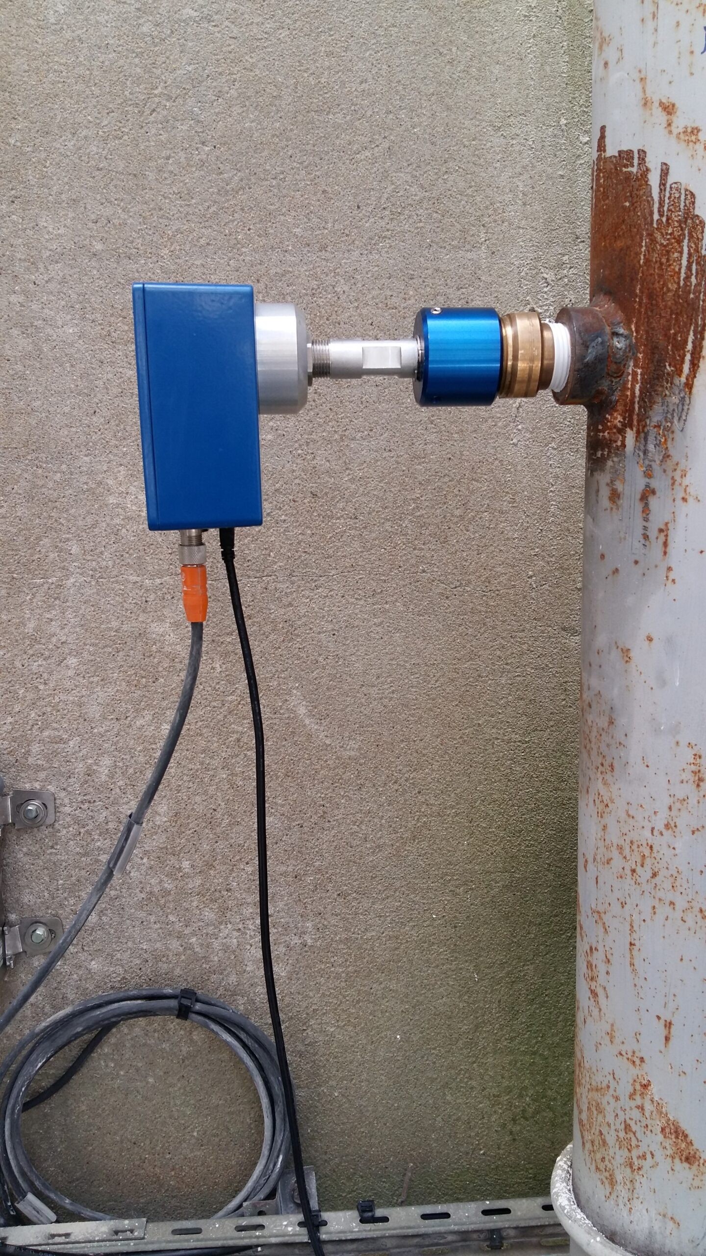
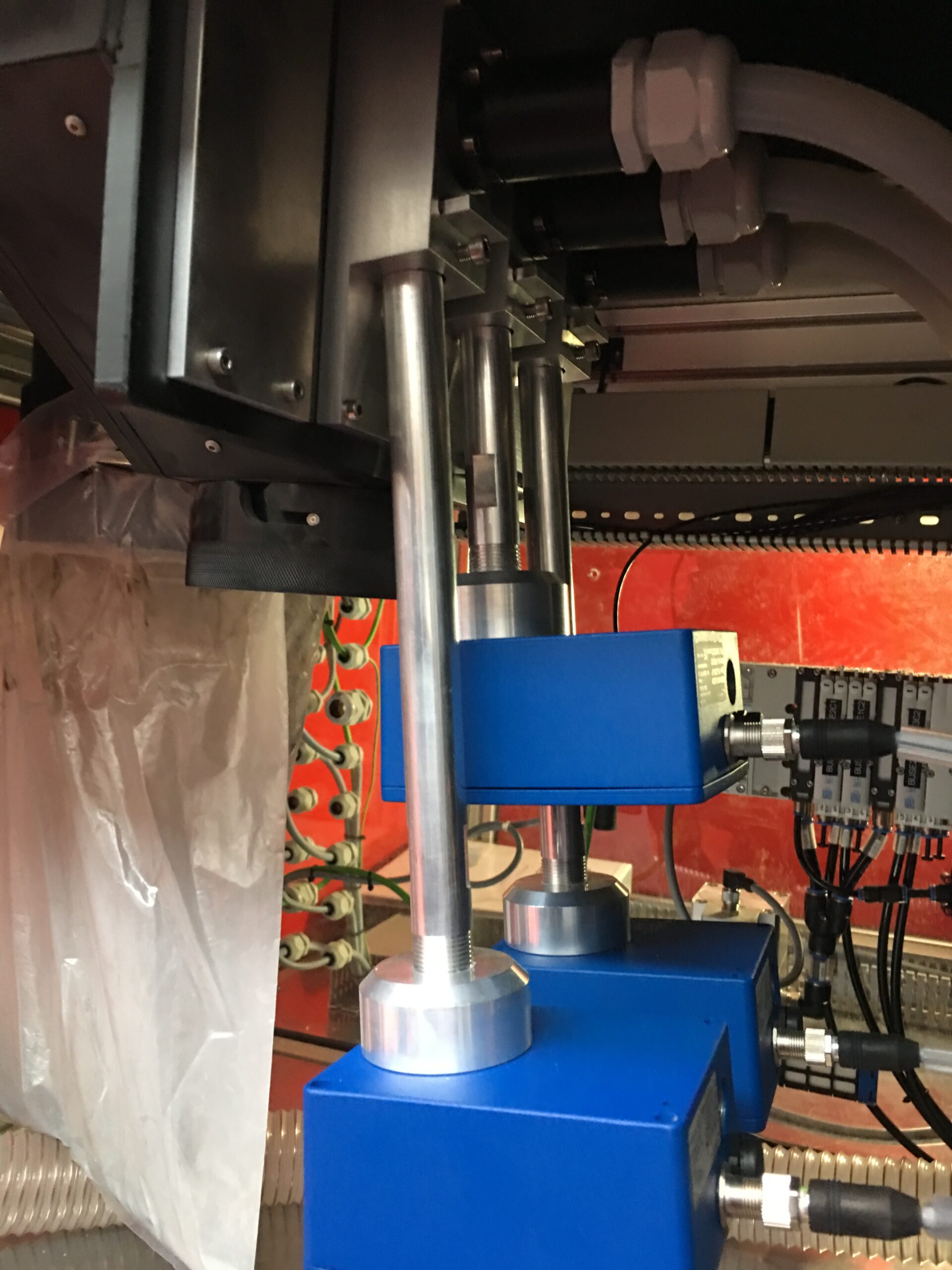
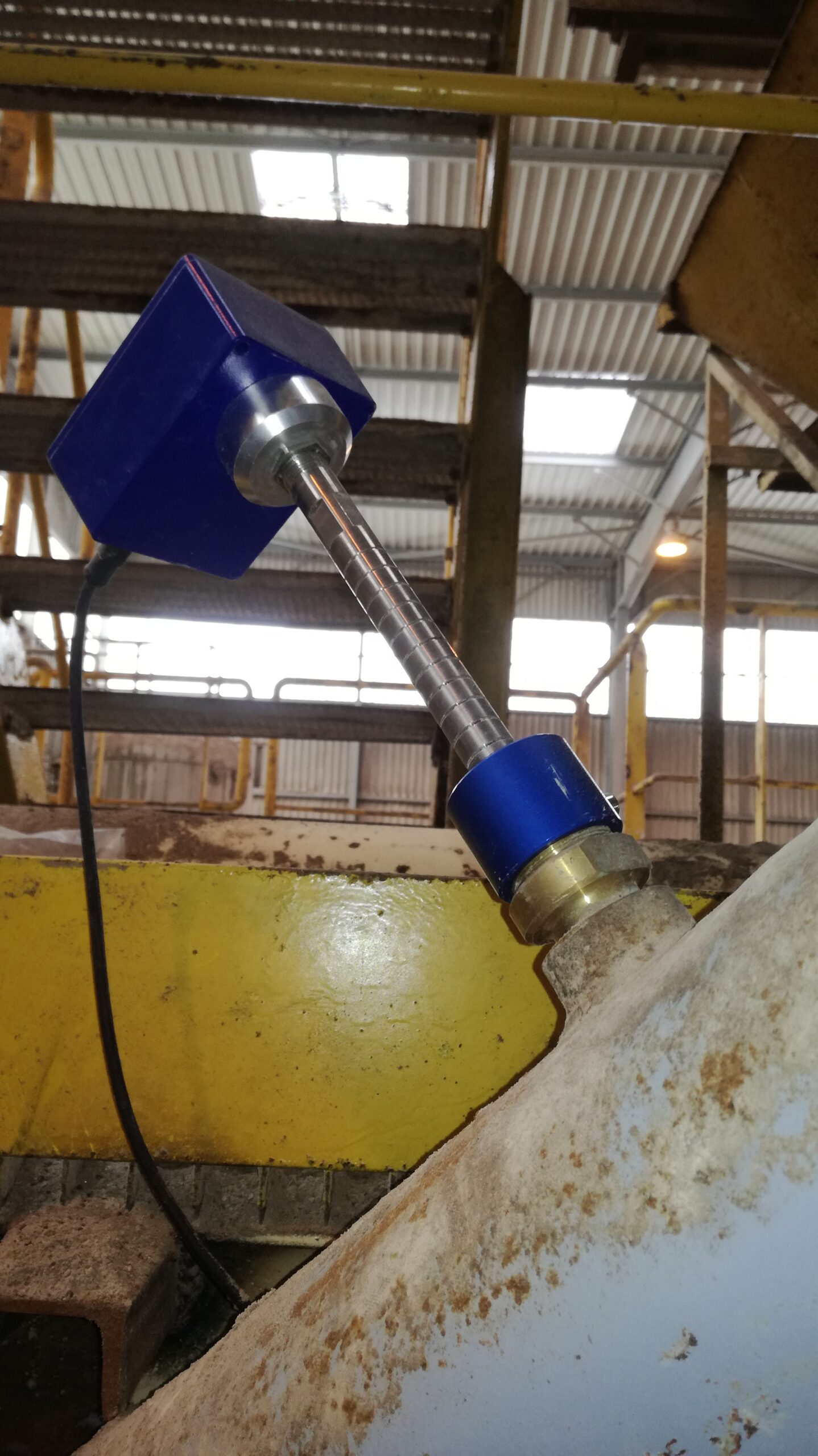
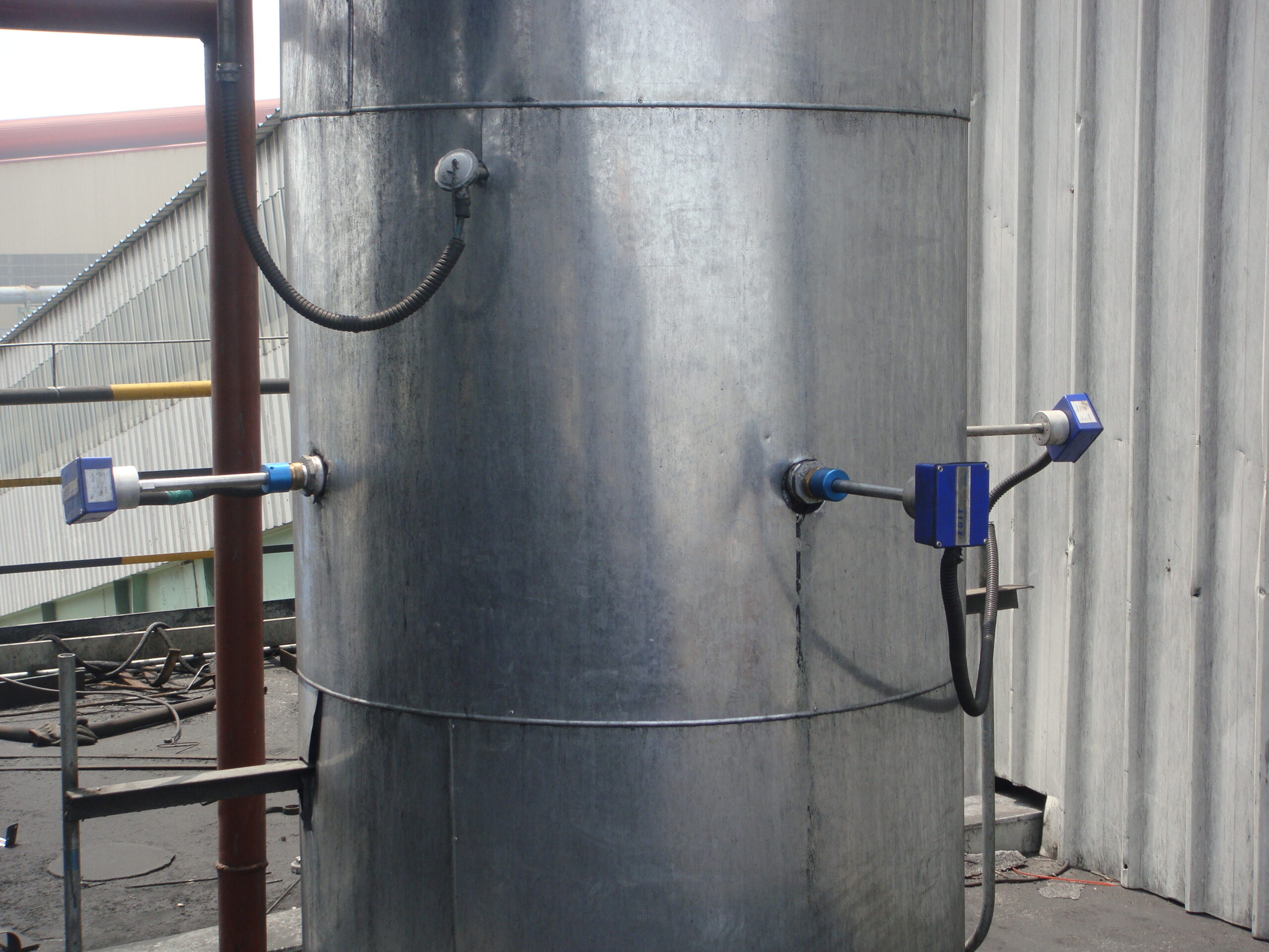
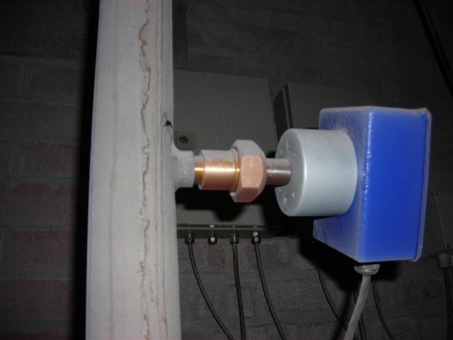
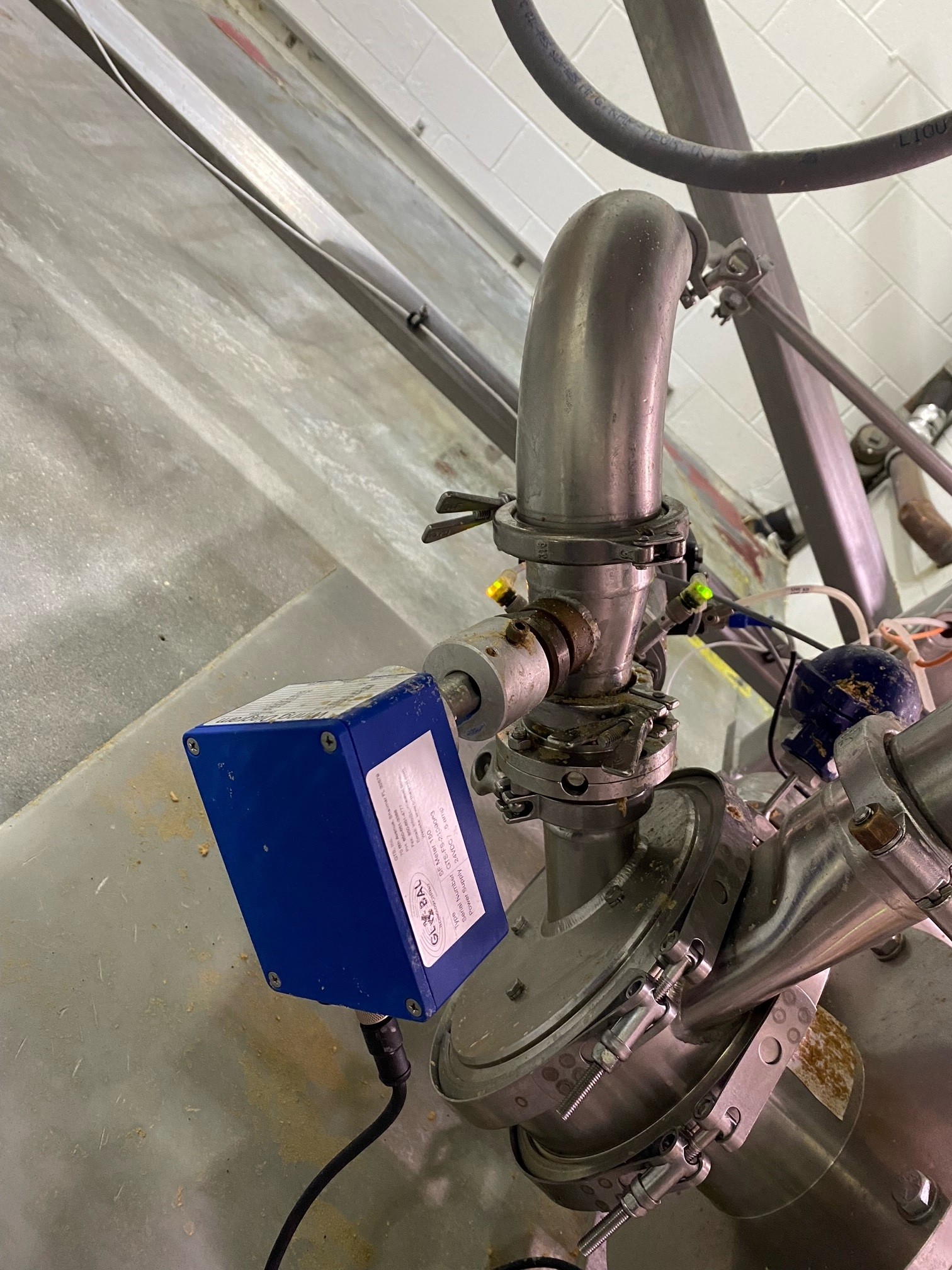
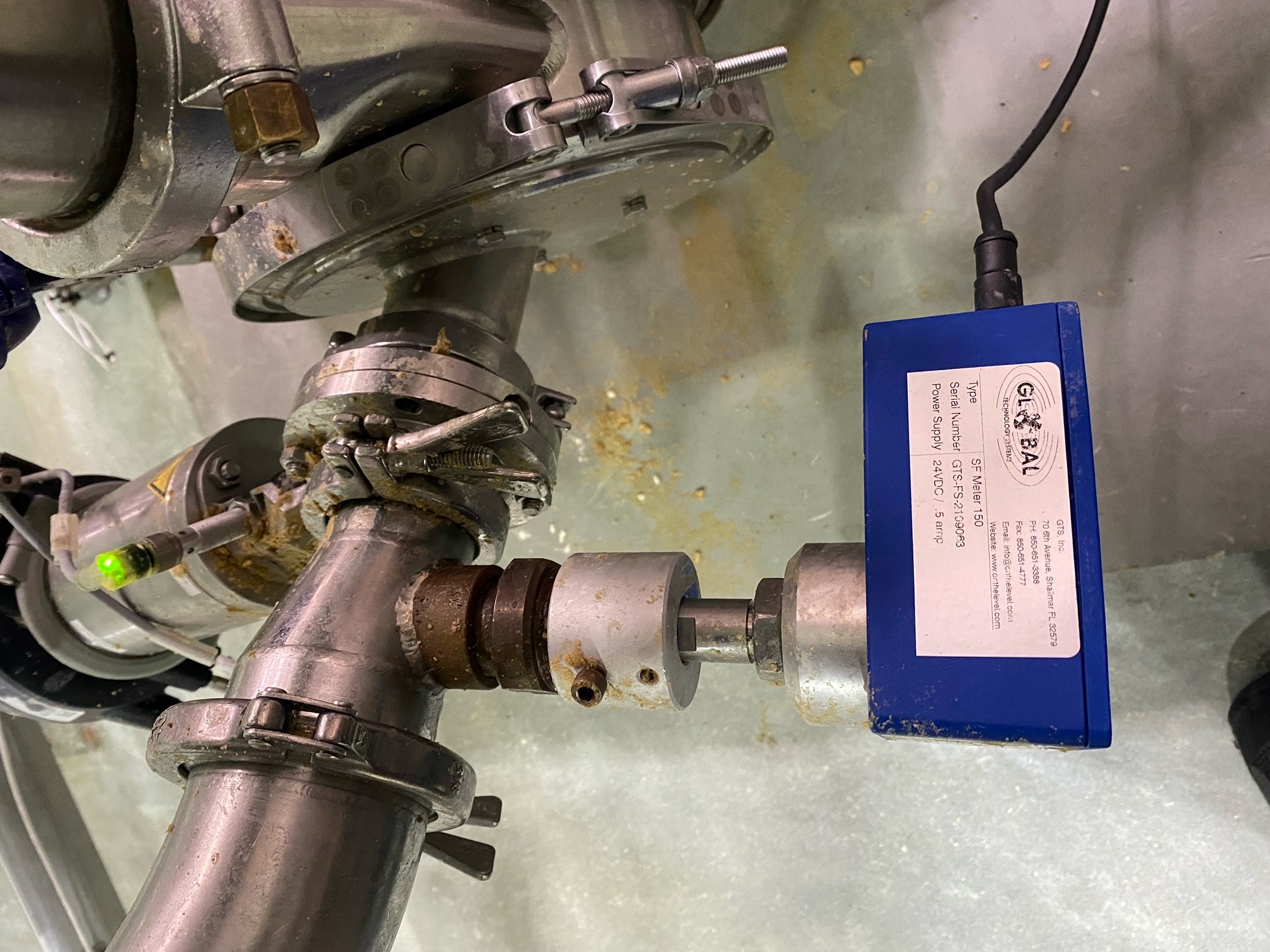
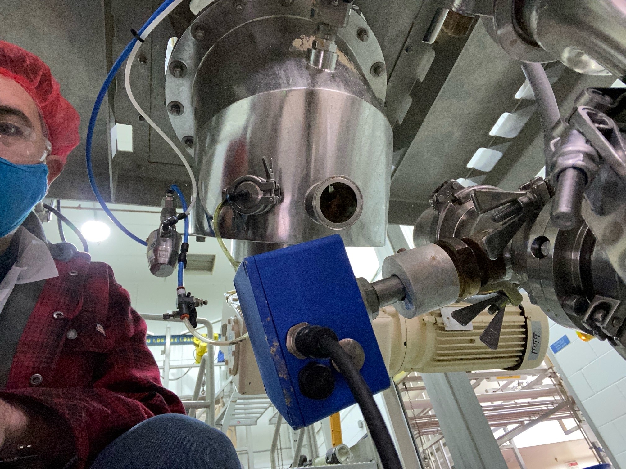
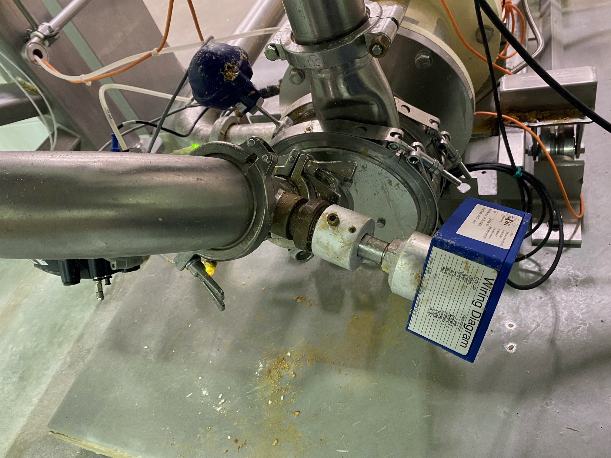
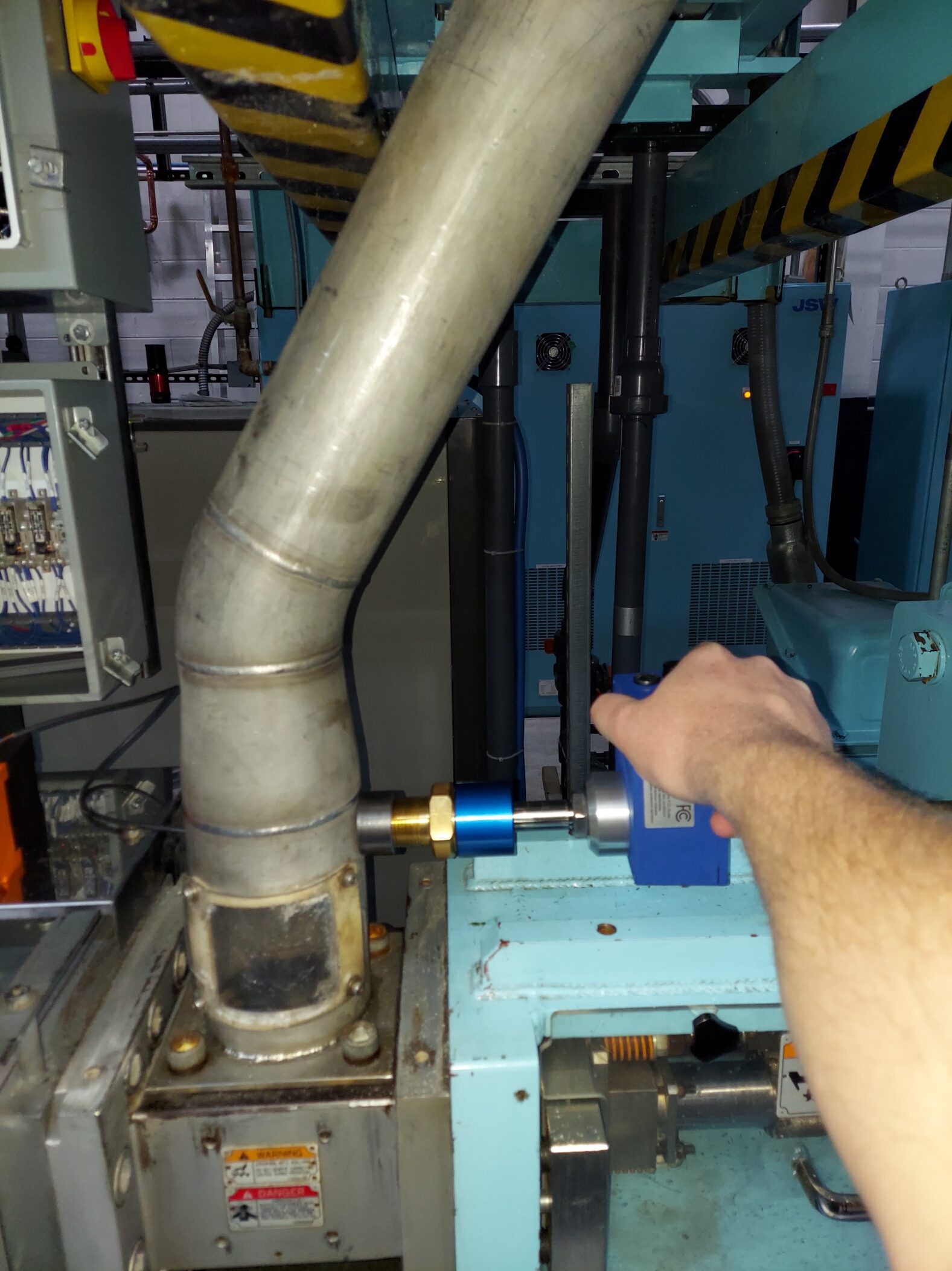
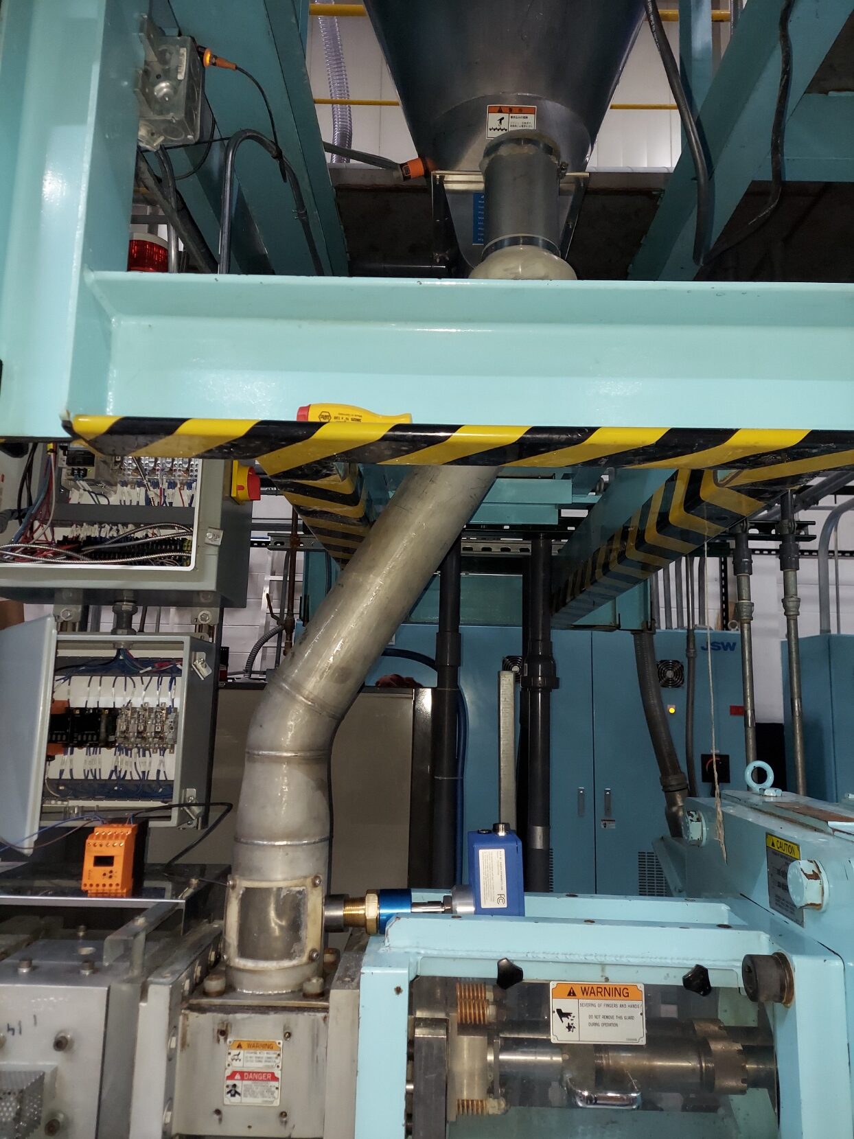
Mounting and Installation
SENSOR MOUNTING PROCEDURE :
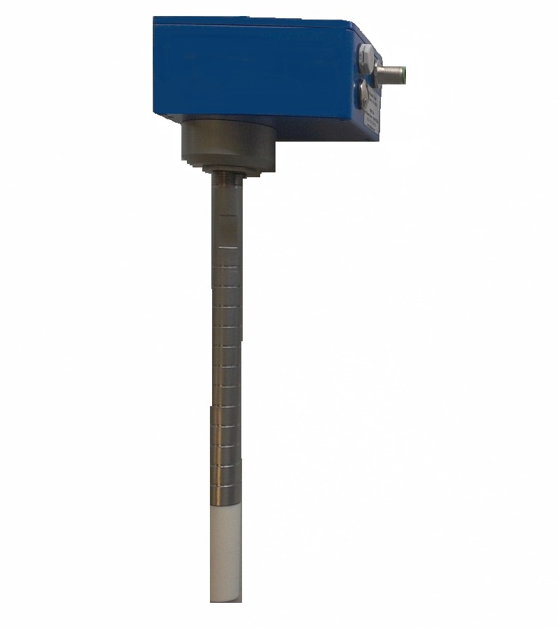
1. Position the circlip on the waveguide regarding depth of the bushing + valve +
bracket + thickness of the pipe.
For optimal operation, the sensor head should be at least flush with the inside of the
pipe or slightly inside.
Use a depth gauge to determine the exact depth
2. Unscrew the headless screws of the blue holder bracket.
3. If you have a valve, open the valve to allow the passage of the waveguide.
4. Insert the waveguide sensor proper depth.
5. Secure the sensor with the screws.
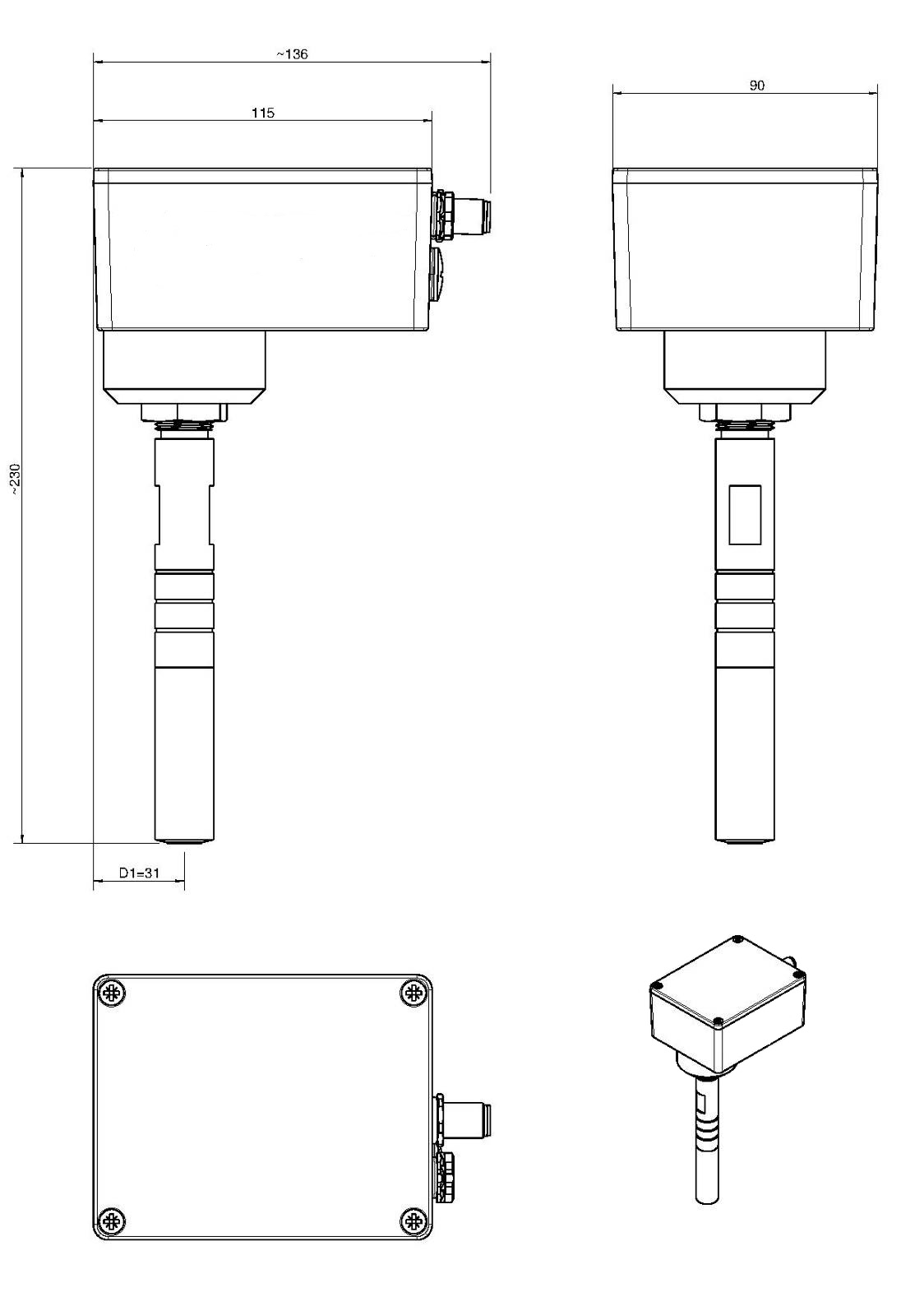
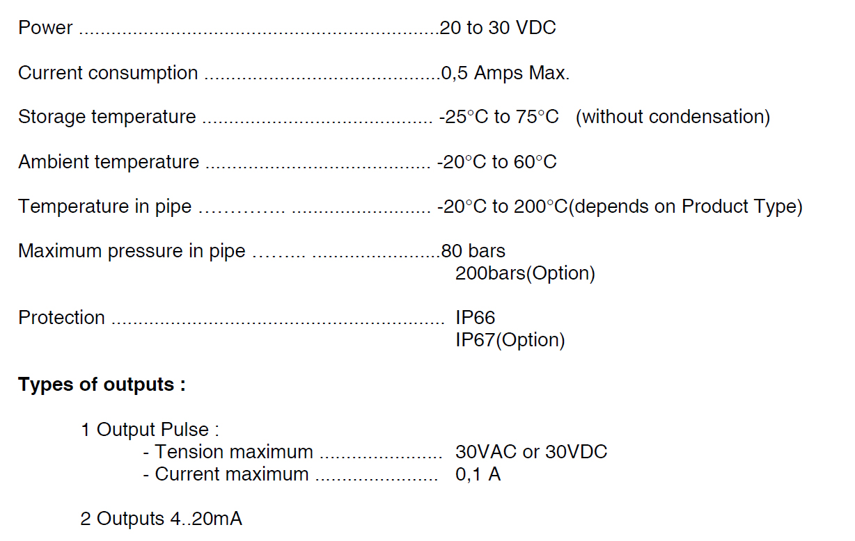
Technical Data
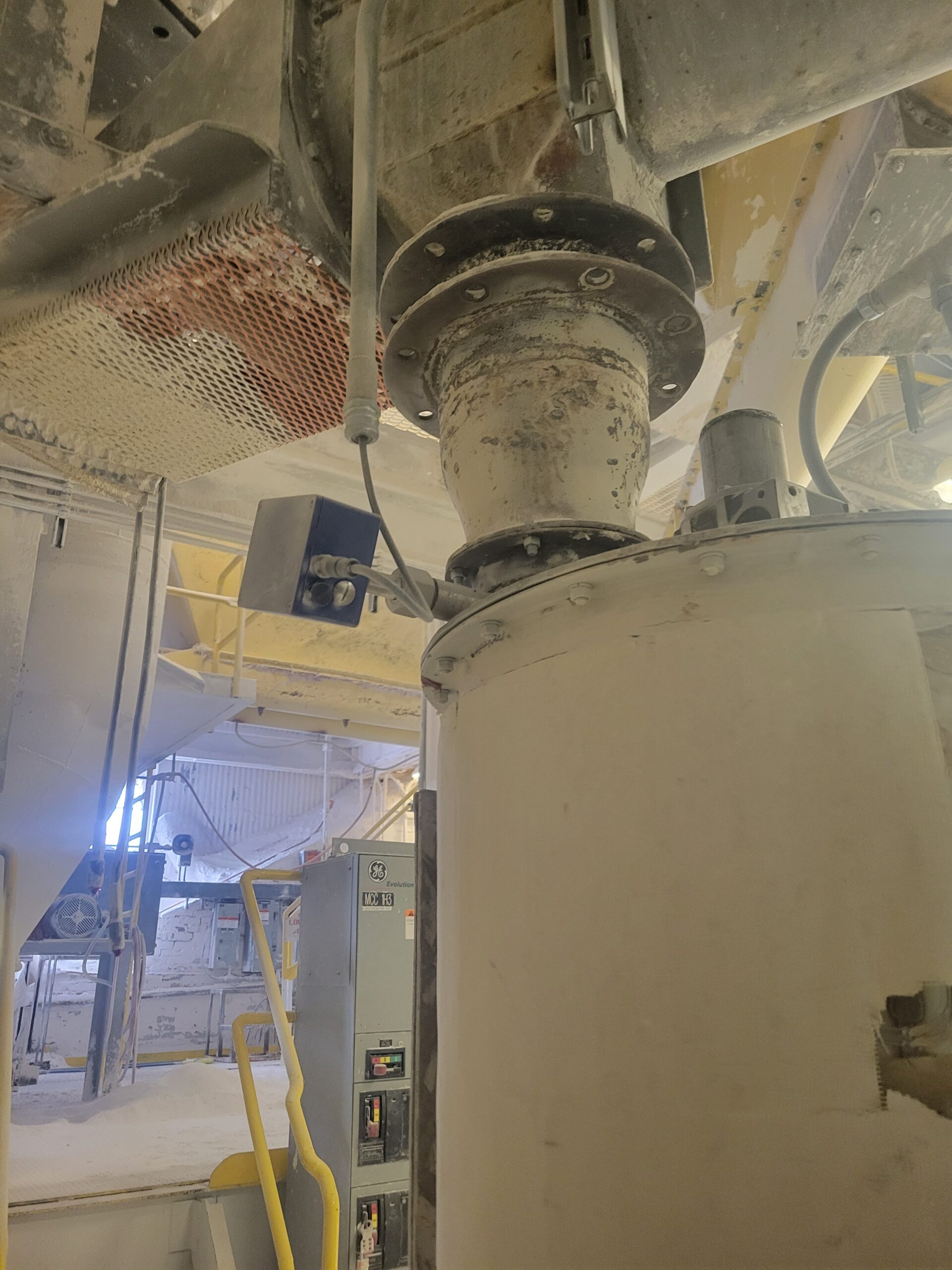
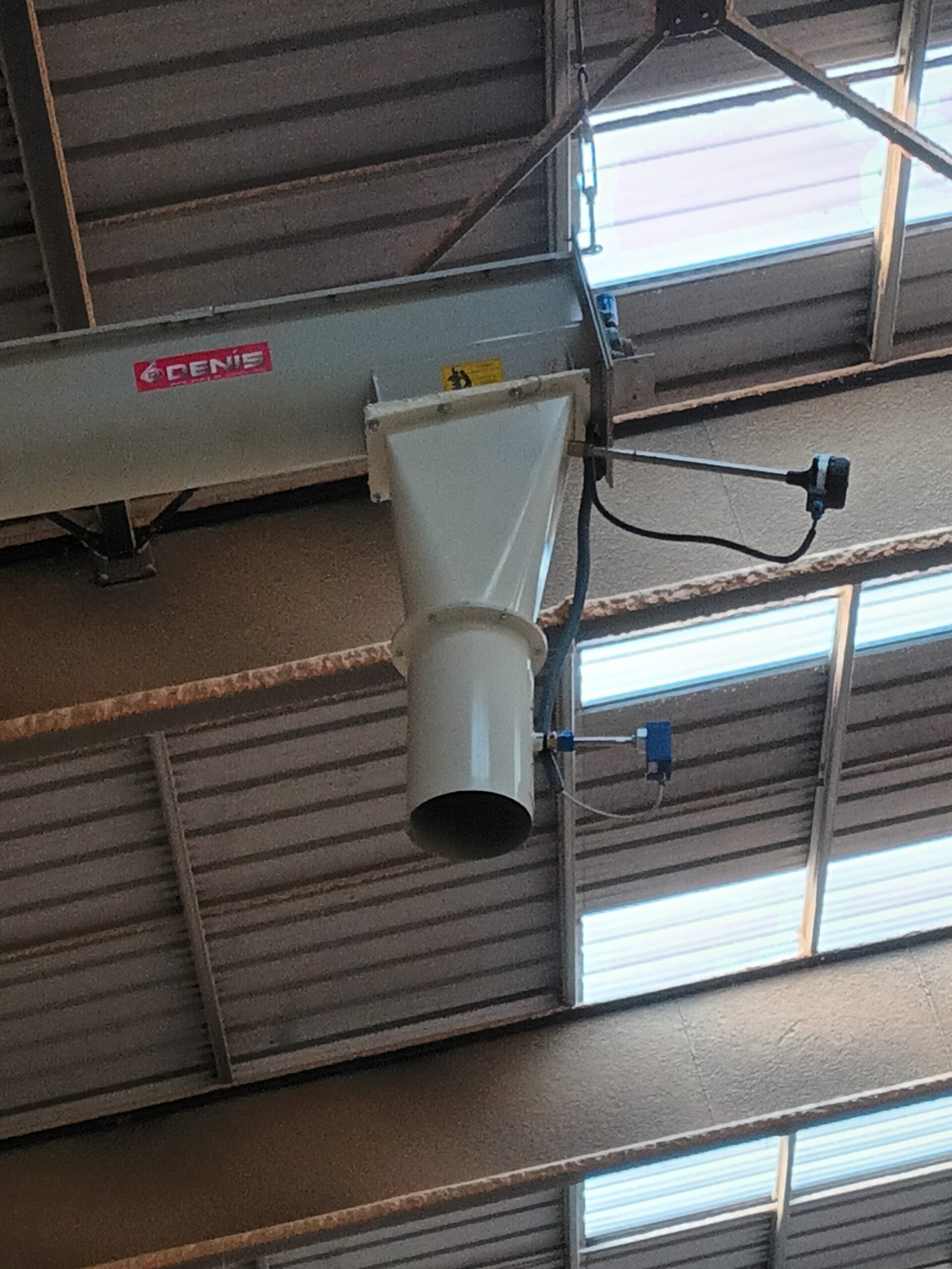
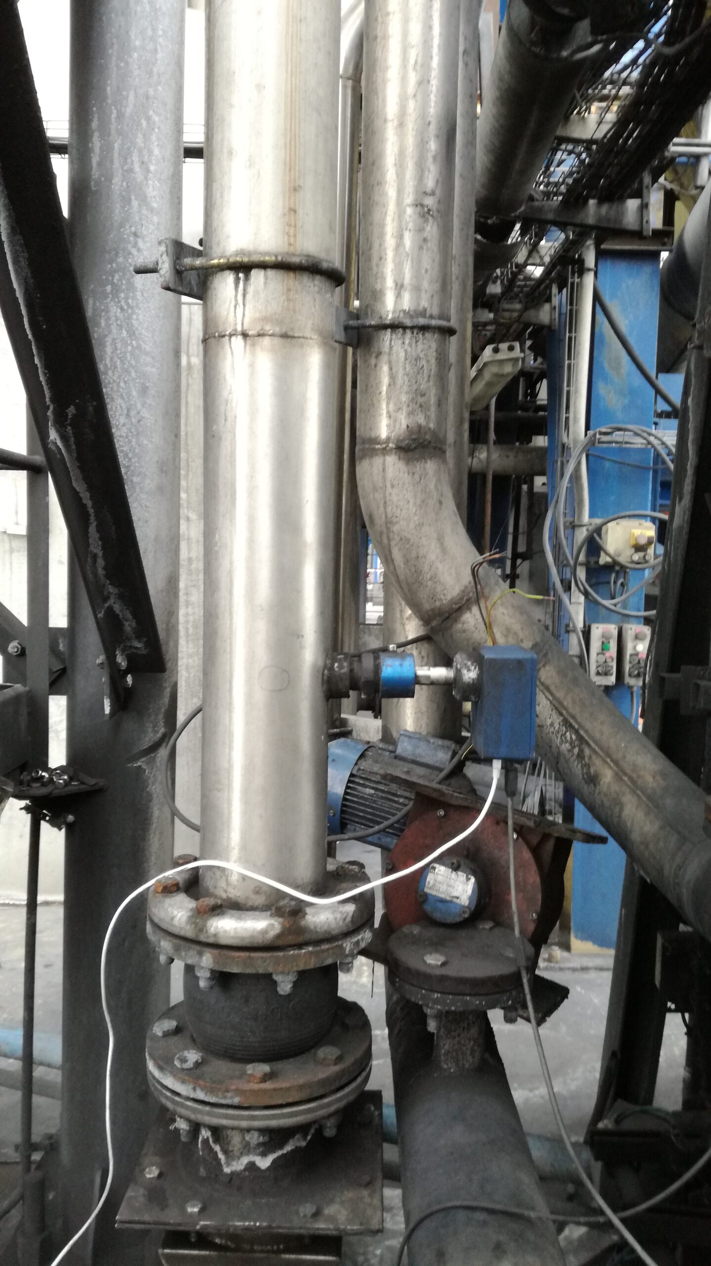
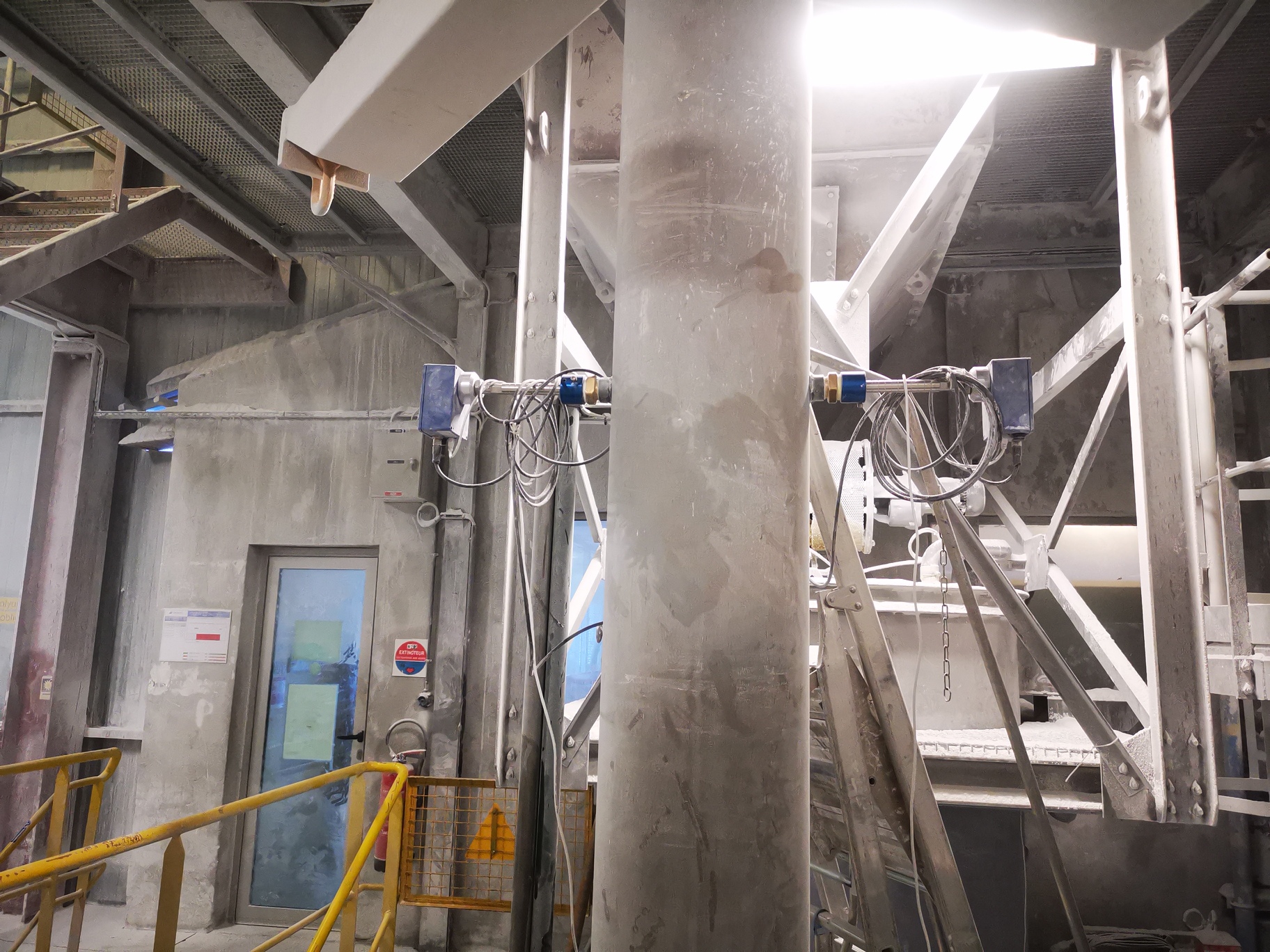
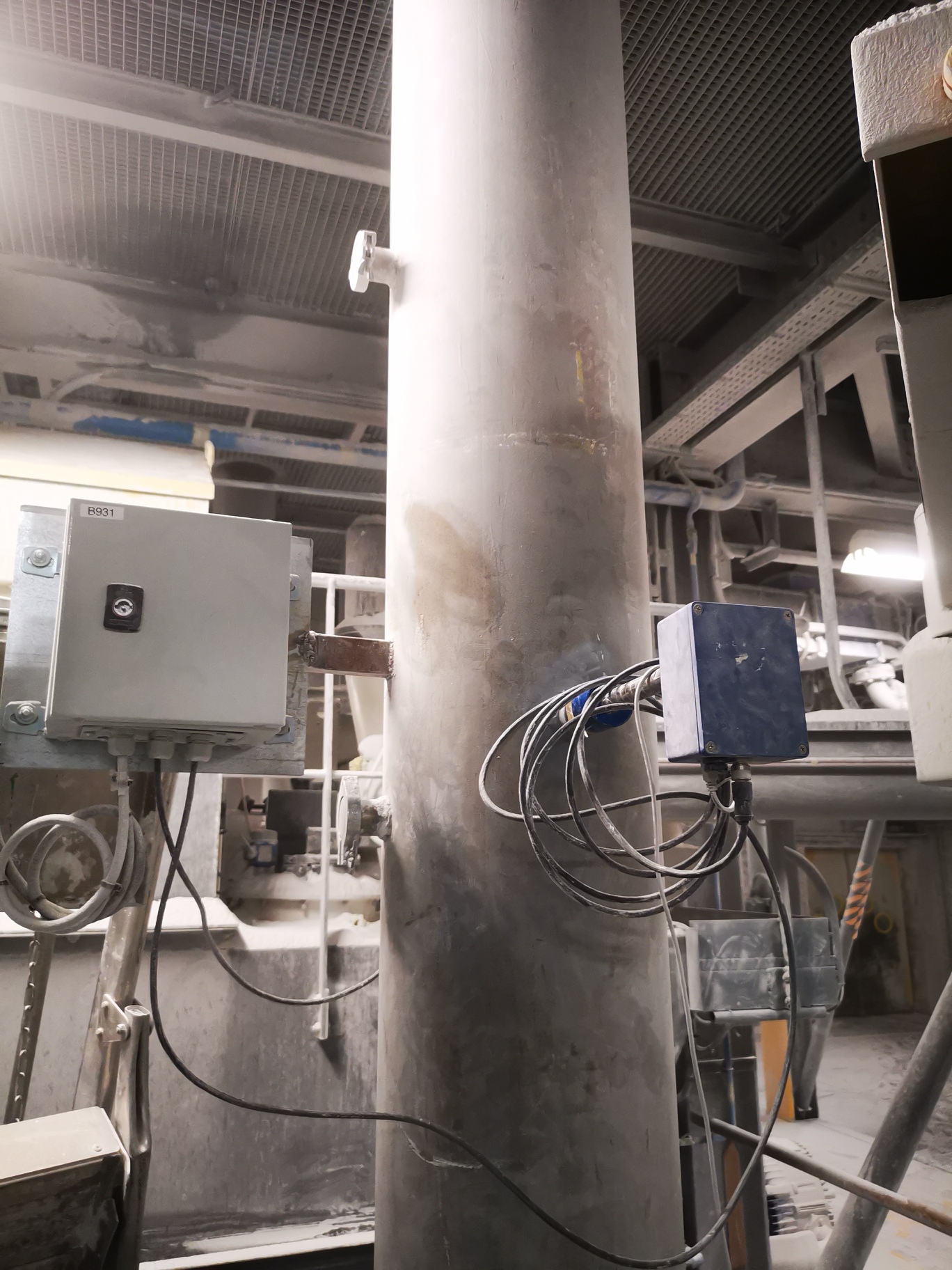
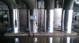
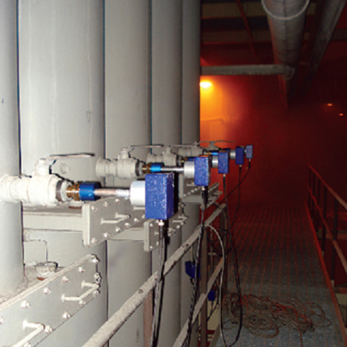
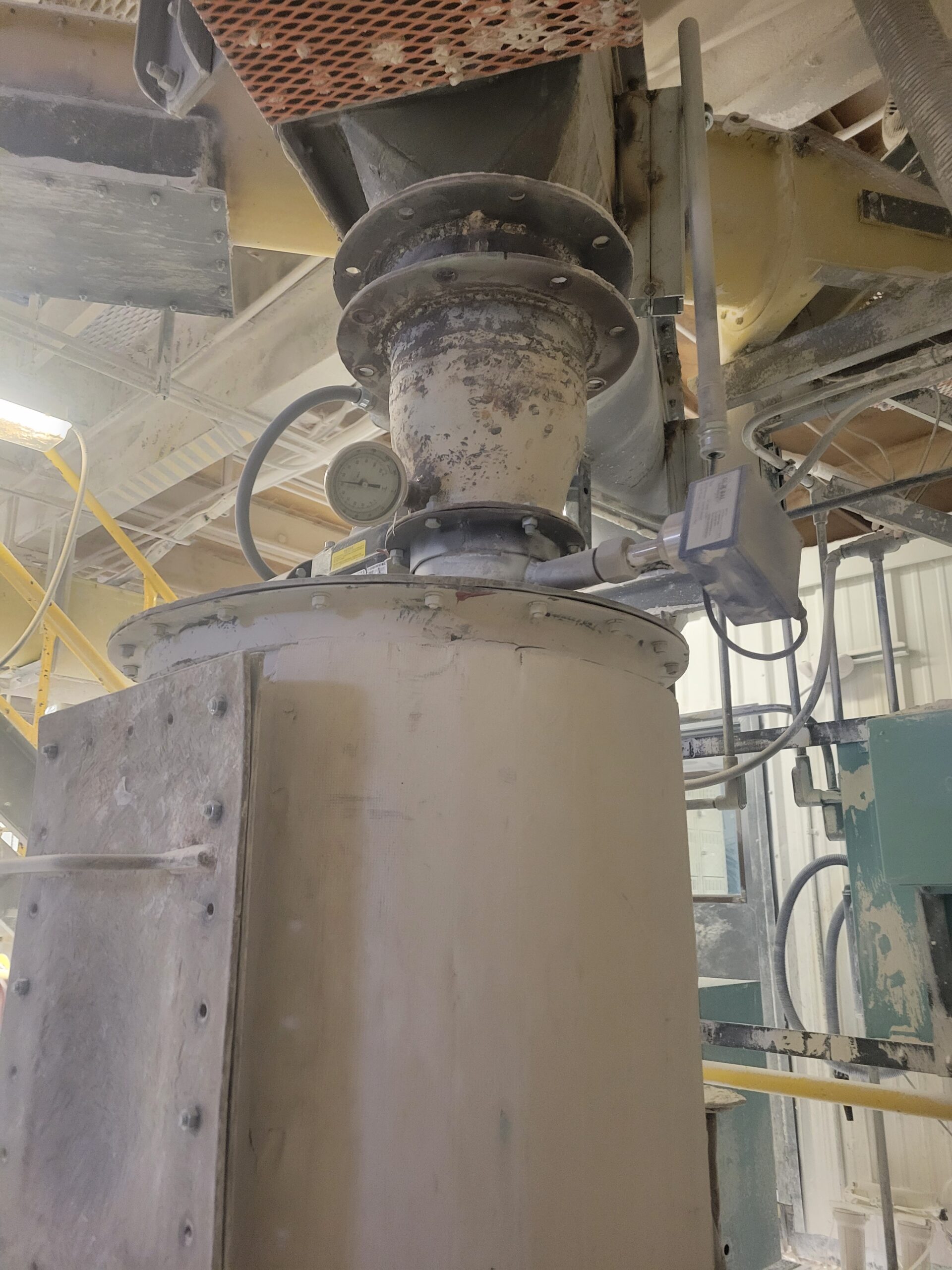
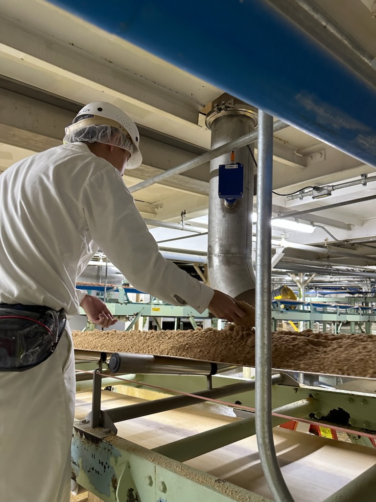
Application Examples
Click on a desired application example to navigate to a detailed description.


Global Technology Systems
P.O. Box 799 Shalimar, FL 32579. USA
(850) 651-3388
Info@onthelevel.com
Partners