MultiFLOW METER
Accurate Mass Flowmeter for Solids in Large Pipes or Chutes
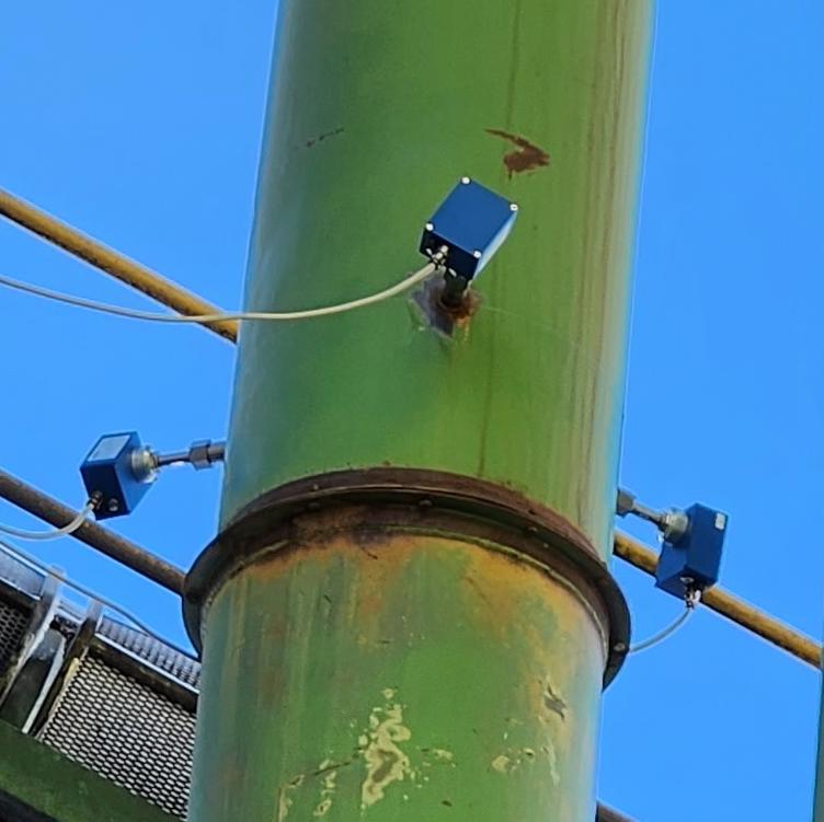
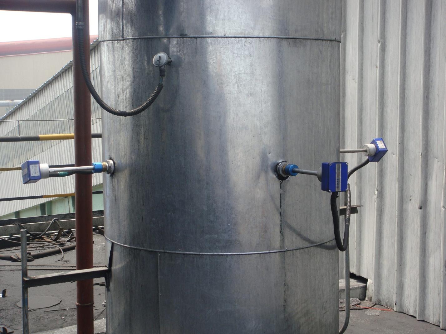
- Triple Sensor Input
- Free fall or Dilute-phase pneumatic conveying
- True Mass Flow Output
- For pneumatic conveying and freefall processes (typically 1 to 400 tph)
- Easy installation and start up procedures for calibration
- Integral solids flow measurement for all types of powders, granules, flakes, chips, etc.
- Install on pipe diameters greater than 8 inches (chutes and ducts need to be reviewed)
- Long-term stable, reliable, and redundant
- Sensor supply for connections up to 1000 m
- Galvanically separated RS485-Interface for PLC-Connection
- Analog 4-20 mA output, RS485 and alarm relay

What do you want to do?
Use
MF METER (Solids Flow) uses the principle of the Doppler effect.
A microwave signal is emitted, thereby generating an electromagnetic field inside the pipes. The particles passing in movement in this field generate a signal that varies in amplitude and frequency. The rate of flow is computed from a mathematical analysis combined with a calibration (with real measurements).
The Smart HMI Controller combines the raw signals of all 3 sensors and produces an accurate overall flow measurement usually within +/- 1-3% FS. This intelligent system compensates for material randomly flowing at different concentrations within the pipe diameter.
Why Use Three MF METERs?
- Eliminates Flow Profile Bias: Product rarely flows uniformly in wide pipes or chutes. Averaging three independent measurements eliminates errors caused by asymmetrical flow.
- Redundant Measurement: Ensures continued operation if one sensor fails.
- Improved Accuracy: Captures localized variations, delivering a reliable overall mass flow value.
Function
Beyond the working principle, the technology developed for MultiFLOW METER allows the equipment to compensate for variations in:
- Concentration
- Speed of particles
- Granulometrics
- Temperature
- Buildup
FOR BETTER PRECISION.
FOR BETTER REPEATABILITY.
FOR BETTER STABILITY OVER TIME.
Contactless measurement
Very easy-to-use device
No maintenance
No remote electronic handling
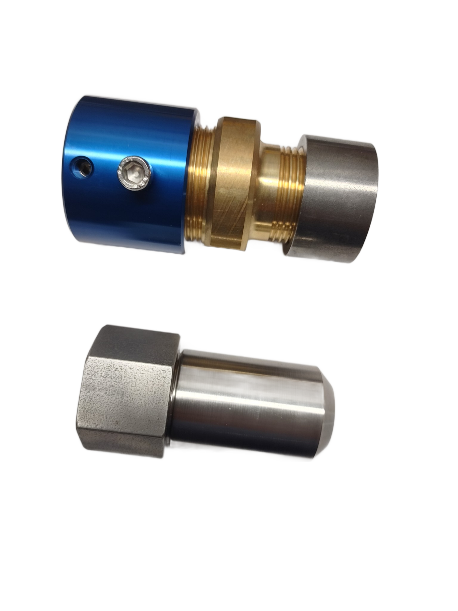
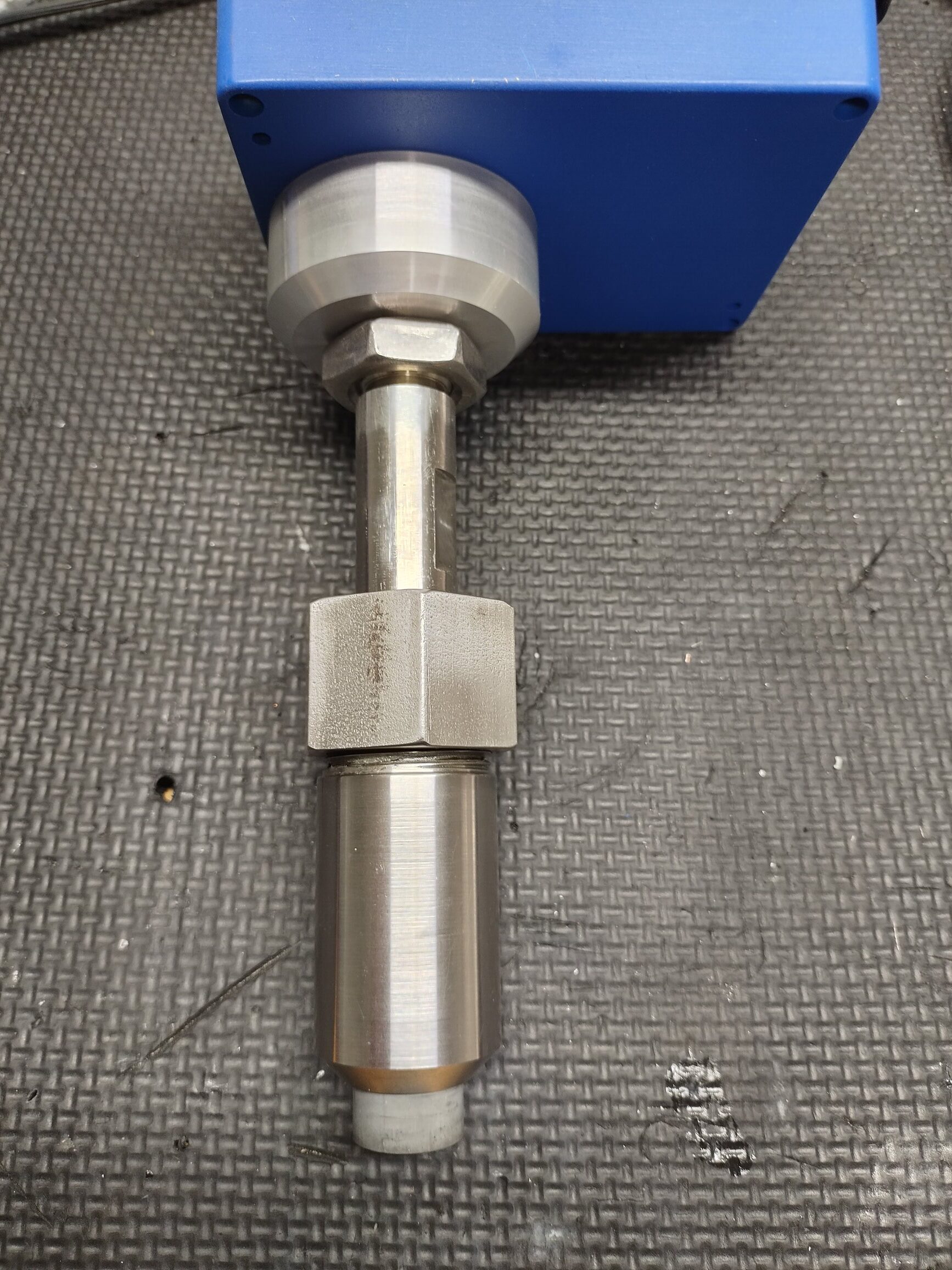
Mounting and Installation
SENSOR MOUNTING PROCEDURE :
- Position the circlip on the waveguide regarding depth of the bushing + valve +
bracket + thickness of the pipe.
For optimal operation, the sensor head should be at least flush with the inside of the
pipe or slightly inside.
Use a depth gauge to determine the exact depth - Unscrew the headless screws of the blue holder bracket.
- If you have a valve, open the valve to allow the passage of the waveguide.
- Insert the waveguide sensor proper depth.
- Secure the sensor with the screws.
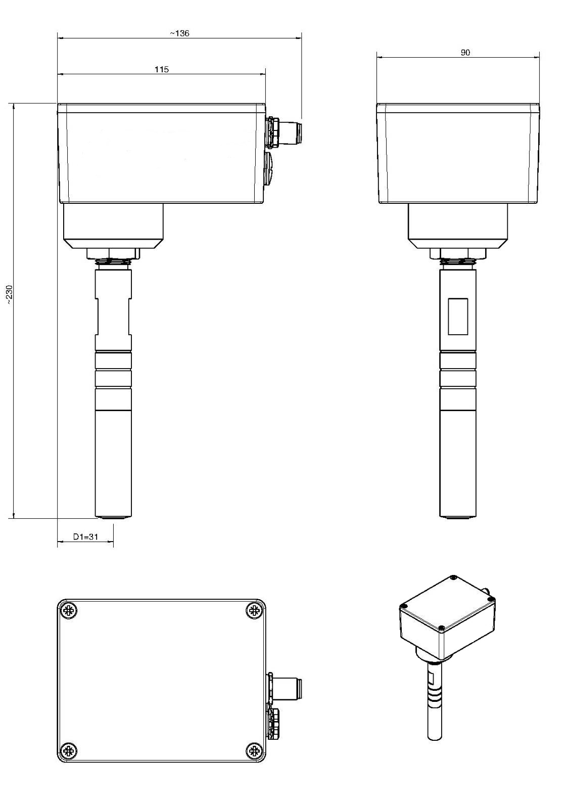
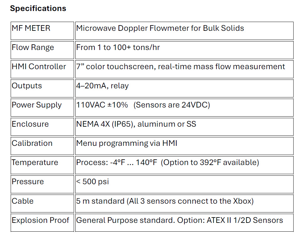
Technical Data
Application Examples
Measuring wood chips in a dilute-phase pneumatic conveyor
Measuring pulverized coal to balance flow into the burner
Global Technology Systems
P.O. Box 799 Shalimar, FL 32579. USA
(850) 651-3388
Info@onthelevel.com
Partners