FLOWguard S
Flow Monitor of powders through small flexible hoses
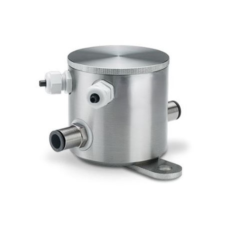
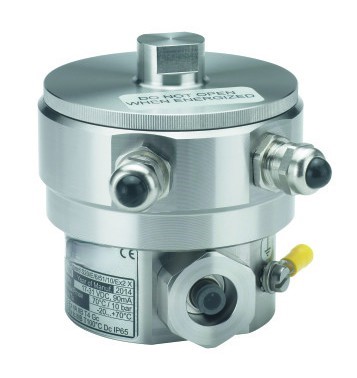
- FLOWguard S has 3 versions for monitoring powders in flexible hoses (T, E, & W)
- Easy installation and start up
- Integral solids flow trending using a 4-20mA output or relay for Flow/ No Flow Alarm
- Install on any size tube/hose from 4 – 38 mm diameter (conductive or non-conductive hoses)
- Long-term stable, reliable, robust and repeatable outputs
- Stainless Steel 1.4305 (AISI 303) housing
- General Purpose or EX versions
- Measures very slow powder movement
What do you want to do?
Use
The FLOWguard S sensor monitors the flow of solids in hose lines and uses a switching output to signal if a set limit value is exceeded or not reached. The version with analog output (4…20 mA) can output a trend.
During the (pneumatic) transport of granules , powders , blasting agents , abrasives , dust or other bulk materials, e.g. B. blockages , an empty storage container, “rat holes” (chimney formation) or bridging over the container discharge are immediately and reliably detected.
The measuring principle is based on the detection of electrical charges, which are naturally present on the particles in the flow of solids and are created, for example, by friction on the wall. Stationary solids are not detected.
The hose line is simply pushed through the measuring device (version T) and fastened with the screw connection. Version E is used for applications on electrically conductive hoses or if the hose has to be cut open for connection.
Give us a call. We would be happy to advise you on the subject of solids flow monitoring.
Function
The FLOWguard S is used to monitor the flow of solids in flexible hoses. It alarms through a relay output when a threshold is exceeded
or trends the flow with the Analog (4-20mA) version. When granulates, powders, blasting material, dust or other solids are (pneumatically) transported; blockages are immediately detected due to an empty feed bin or plug condition.
The measurement principle is based on the detection of moving electrical charges which naturally adhere to the solids surface
and are produced e.g. through friction on the hose-wall. Only moving particles generate a signal.
The hose is simply passed through the instrument (version T) and is tightened with the hose fittings.
In applications with conductive hoses, for larger diameters or in cases where the hose must be cut for installation, the versions E
or W are used. Here the hose is plugged into hose fittings or fixed on nozzles from two sides.
The device cannot be used if bulk solids build up an electrically conductive layer on the inner hose wall.
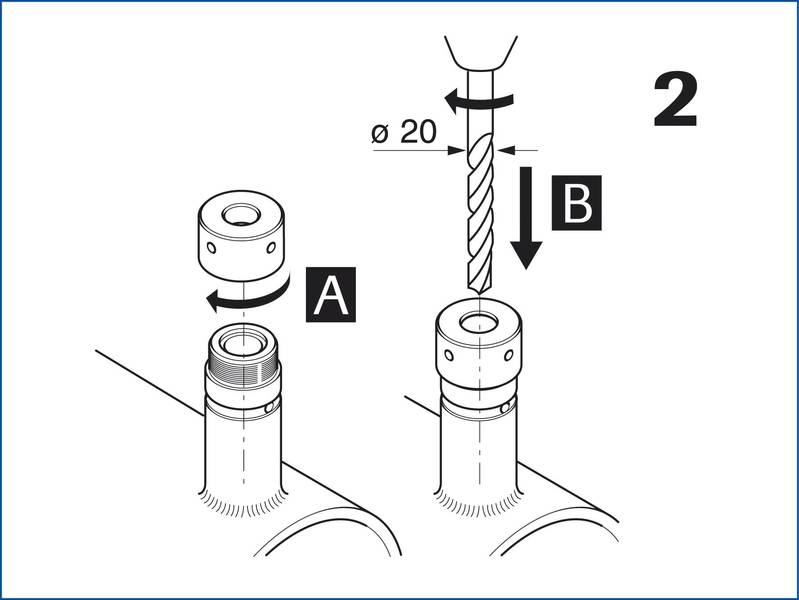
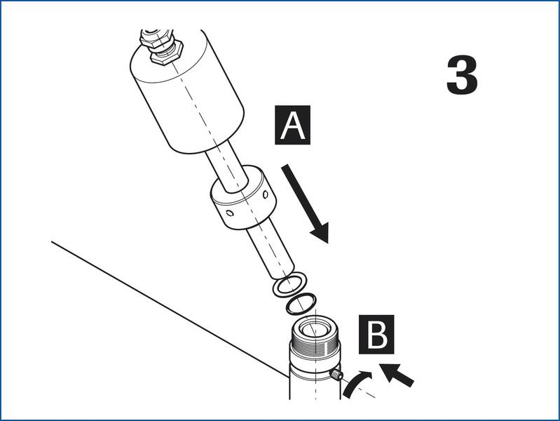
Mounting and Installation
Technical Specifications and Mechanical Structure of the S…E Version
Individual parameters depend on the device version and can be found in the device name. The device names are itemised in chapter 10.
Fig. 7 Specifications and mechanical structure of Flow-Guard S…E Dimensions in mm (in.)
1 Screw cap (stainless steel 1.4305 (AISI 303))
2 Cable inlet M16 x 1.5
3 Head housing l (stainless steel 1.4305 (AISI 303))
4 Hose connection
5 Hose (not included)
|
Ø OD |
Ø ID |
L |
|
4 |
2.7 |
113 (4.45) |
|
6 |
4 |
116 (4.57) |
|
8 |
6 |
132 (5.20) |
|
10 |
8 |
129 (5.08) |
|
12 |
10 |
144 (5.67) |
|
14 |
12 |
146 (5.75) |
|
16 |
13 |
155 (6.10) |
Tab. 10 Hose-dependent dimensions in mm (in.)
|
Parameter |
Value |
|
Permissible process temperature |
-20 … +70°C (-4 … +158°F) |
|
Permissible process pressure |
10 bar (140 lbs) |
|
Weight |
1.5 kg |
Tab. 11 Technical specifications for S…E version
3.3.1 Technical Specifications and Mechanical Structure of the S…T Version
Individual parameters depend on the device version and can be found in the device name. The device names are itemised in chapter 10.
Fig. 8 Technical specifications and mechanical structure of Flow-Guard S…T Dimensions in mm (.in)
1 Screw cap (stainless steel 1.4305 (AISI 303))
2 Cable inlet M16 x 1.5
3 Head housing l (stainless steel 1.4305 (AISI 303))
4 Hose inlet
5 Hose (not conductive, not included)
|
Parameter |
Value |
|
Permissible process temperature |
-20 … +70°C (-4 … +158°F) |
|
Permissible process pressure |
Specified by hose |
|
Weight |
1.6 kg |
Tab. 12 Technical specifications for S…T version
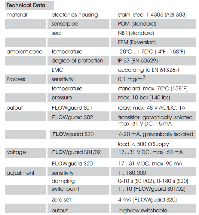
Technical Data
Global Technology Systems
P.O. Box 799 Shalimar, FL 32579. USA
(850) 651-3388
Info@onthelevel.com


