
Solids flow meters
MultiFLOW Meter Mass Flow Meter for Large Pipes and Chutes
Three microwave sensors and a smart HMI controller that combine into one accurate mass flow reading for solids in large pipes or chutes, in free fall or dilute-phase pneumatic conveying.
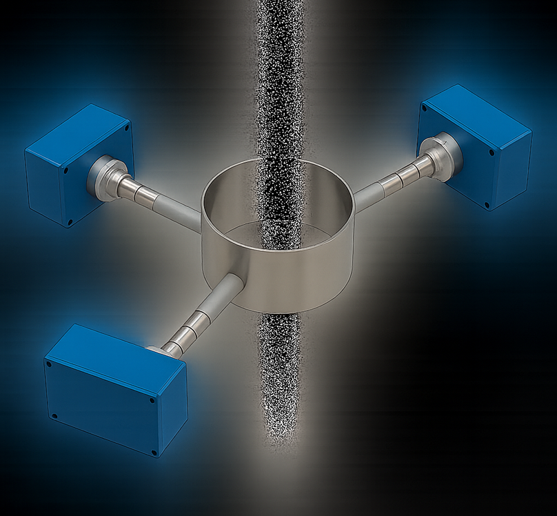
- Triple sensor input
- Free fall or dilute-phase pneumatic conveying
- True mass flow output
- For pneumatic conveying and free-fall processes, typically 1 to 400 tph
- Easy installation and start-up procedures for calibration
- Integral solids flow measurement for powders, granules, flakes, chips and more
- Installs on pipe diameters greater than 8 inches (chutes and ducts need to be reviewed)
- Long-term stable, reliable and redundant
- Sensor supply for connections up to 1000 m (3,280 ft)
- Galvanically separated RS485 interface for PLC connection
- Analog 4–20 mA output, RS485 and alarm relay
Use
Where the MultiFLOW Meter fits
Each MF Meter (Solids Flow) uses the Doppler effect. A microwave signal is emitted, generating an electromagnetic field inside the pipe. Particles moving through this field produce a signal that varies in amplitude and frequency. The flow rate is computed from a mathematical analysis combined with a calibration against real measurements.
The Smart HMI Controller combines the raw signals of all three sensors and produces an accurate overall flow measurement, usually within ±1–3% of full scale. The system compensates for material flowing at different concentrations across the pipe diameter.
Why use three MF Meters?
- Eliminates flow profile bias. Product rarely flows uniformly in wide pipes or chutes. Averaging three independent measurements removes errors caused by asymmetrical flow.
- Redundant measurement. Operation continues if one sensor fails.
- Improved accuracy. Localized variations are captured, giving a reliable overall mass flow value.
Function
Compensation for changing process conditions
Beyond the working principle, the technology developed for the MultiFLOW Meter lets it compensate for variations in:
- Concentration
- Particle speed
- Particle size distribution
- Temperature
- Buildup
The result is better precision, better repeatability and better stability over time.
- Contactless measurement
- Very easy to use
- No maintenance
- No remote electronics to handle
Mounting and installation
Sensor mounting procedure
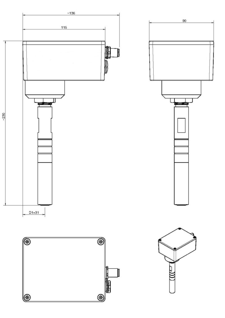
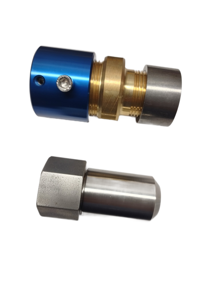
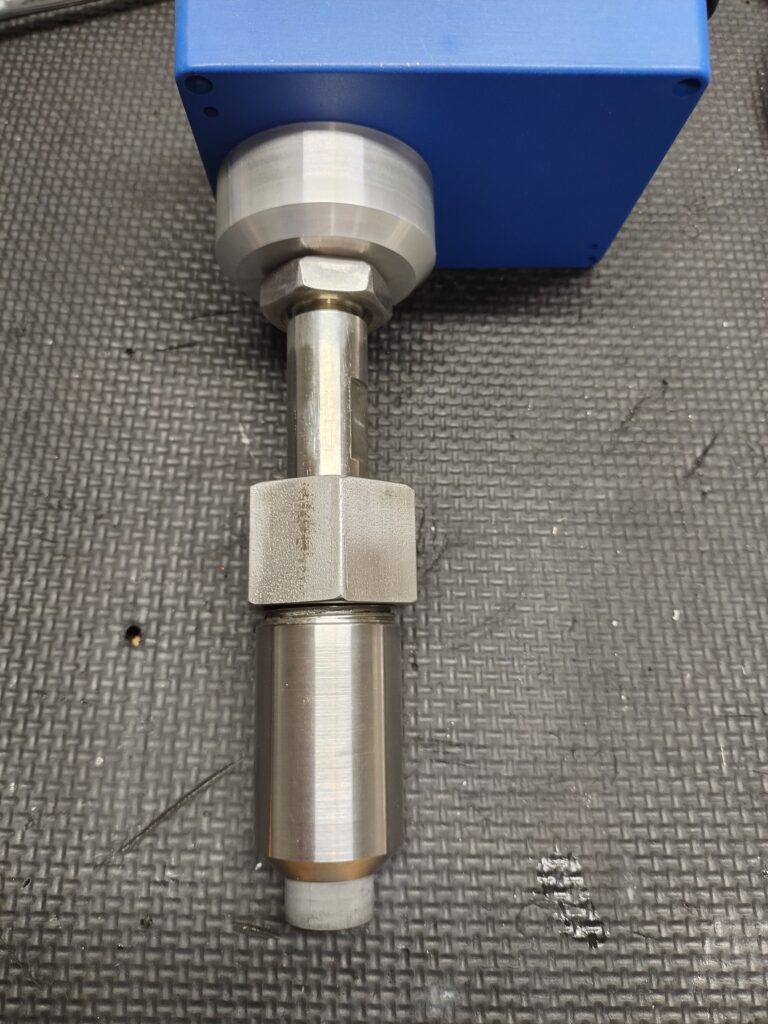
- Position the circlip on the waveguide to suit the combined depth of the bushing, valve, bracket and pipe wall. For best results the sensor head should sit flush with the inside of the pipe, or slightly inside it. Use a depth gauge to find the exact depth.
- Unscrew the headless screws on the blue holder bracket.
- If a valve is fitted, open it so the waveguide can pass through.
- Insert the waveguide sensor to the correct depth.
- Secure the sensor with the screws.
Technical data
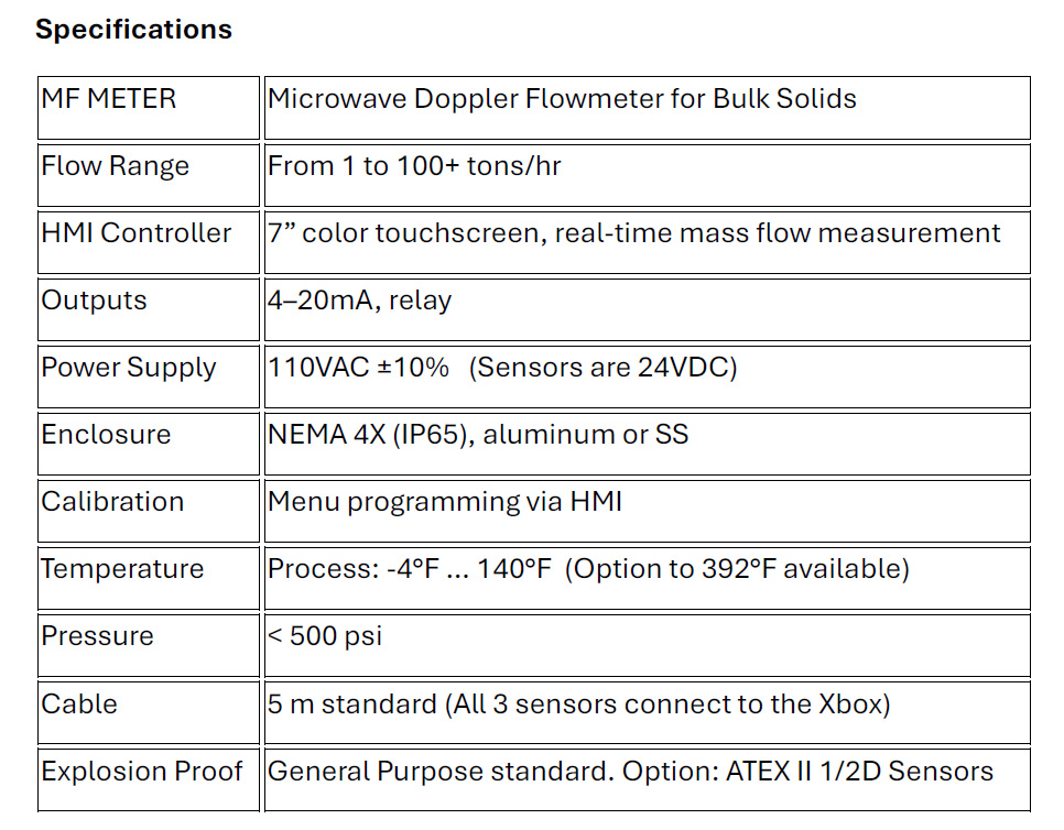
MultiFLOW Meter specifications
Transcribed from the product brochure, with metric conversions added. Confirm critical values against the brochure PDF.
| MF Meter | Microwave Doppler flow meter for bulk solids |
|---|---|
| Flow range | From 1 to 100+ tons/hr |
| HMI controller | 7 in color touchscreen, real-time mass flow measurement |
| Outputs | 4–20 mA, relay |
| Power supply | 110 V AC ±10% (sensors are 24 V DC) |
| Enclosure | NEMA 4X (IP65), aluminum or stainless steel |
| Calibration | Menu programming through the HMI |
| Temperature | Process: −4 to 140 °F (−20 to 60 °C)Option to 392 °F (200 °C) available |
| Pressure | Less than 500 psi (34.5 bar) |
| Cable | 5 m (16.4 ft) standard; all three sensors connect to the Xbox junction |
| Explosion protection | General purpose standardOption: ATEX II 1/2 D sensors |
Application examples
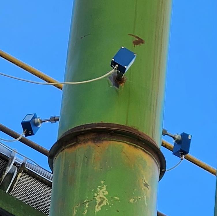
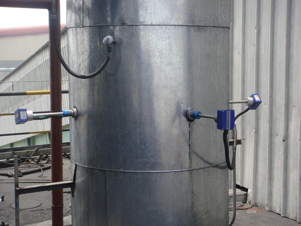
MultiFLOW Meter in real processes
Common questions
MultiFLOW Meter FAQ
Why does the MultiFLOW Meter use three sensors?
Product rarely flows uniformly in wide pipes or chutes. Averaging three independent measurements removes errors caused by asymmetrical flow, keeps the system running if one sensor fails, and captures localized variations for a reliable overall mass flow value.
How accurate is the MultiFLOW Meter?
The Smart HMI Controller combines the three sensor signals into an overall flow measurement that is usually within ±1–3% of full scale.
What pipe sizes is the MultiFLOW Meter for?
Pipe diameters greater than 8 inches. Chutes and ducts need to be reviewed first.
What materials can the MultiFLOW Meter measure?
All types of powders, granules, flakes and chips, in free fall or dilute-phase pneumatic conveying.
What outputs does the MultiFLOW Meter provide?
An analog 4–20 mA output, a galvanically separated RS485 interface for PLC connection, and an alarm relay.
How does the MultiFLOW Meter measure flow?
Each sensor uses the Doppler effect. A microwave signal creates an electromagnetic field inside the pipe, and moving particles produce a signal that varies in amplitude and frequency. The flow rate is computed from that signal and a calibration against real measurements.
Talk with GTS
Is MultiFLOW Meter right for your material?
Tell us what you're conveying, the pipe size and how it moves. We'll confirm whether MultiFLOW Meter fits or recommend a better measurement principle.